MegaShift™ Vehicle Speed Sensor
Speed is a critical factor for your MegaShift™ controller in determining the shifting/TCC behavior, etc. so it really needs to be right.
| Alternate Vehicle Speed Sources
If you are using and engine controller that has a vehicle speed input, such as MS3, MShift™ code can use the speedo signal from that ECU (i.e. MS3). The VSS is connected to MS3, not MShift™/GPIO board. Some users have reported good results doing this. There is more information on how to do this here:
If using the engine controller for the speed input, please see your engine controller's manual for how to set it up properly and troubleshoot issues.
|
Some people have trouble with tuning the the MShift™ speedo to maintain a stable and accurate reading, but such problems are not consistent from one install to the next, and seem to have more to do with electrical noise in the particular installation than the model of the transmission or vehicle.
The more you filter the noise, though, the more of the VSS signal you loose. This is the compromise you have to make when filtering out noise, unfortunately. Squelching the noise inevitably means less speedometer sensitivity. The only way around the low speed filtering compromise is to eliminate the noise from the signal itself. That means twisted pairs for the signal, grounded shielding, great power grounds, etc., etc. (see below).
Noise can be dealt with in hardware and/or in software.
Software:
If you are experiencing VSS issues, the first step is to upgrade to the latest code, as improvements the the VSS interrupt handling are being made frequently. Code can be found here:
If the speedometer still misbehaves, then you might try setting:
That should allow for much more software filtering, and let you see if noise is the issue and it you can sort in in software, or need to do more hardware troubleshooting.
If you are experiencing speedo drop-out issues (sudden drops to zero mph that recover quickly) you need less filtering, so you might try disabling the VSS filtering altogether by setting the VSS input masking to 0 to see if that helps.
Next, try lowering the 'Minimum Vehicle Speed' next, if you haven't already. The minimum speed isn't used for filtering, instead it sets a speed below which no filtering is used (to allow the speedo to reset itself, and allow it to pick up slow speed signal despite any lingering filtering factors). Not having filtering may make your speedo jumpy at low speeds. The default minimum speed is ~3.0 mph, you might try 1.0 or 1.5. Do not set it to 0 unless you want to turn the filtering off entirely. You could also reduce the "reset filter off" time, to make the filtering come back more quickly. If lowering the minimum speed doesn't help, try raising it (perhaps to 5 or 8 mph) to see if that helps. If it does, experiment to find the optimal value.
You can also experiment with the 'Max. Errors to Reset' parameter. This values sets the number of VSS errors that are seen before the system resets (and no filtering is used for a brief time). You might have to raise or lower the maximum number of errors. Try different values to see what works best for your installation.
Hardware:
If you experience vehicle speed sensor problems (indicated by an unstable or non-functioning speedometer in TunerStudioMS) despite experimenting with the software filter settings, you will also want to:
- Make sure the VSS connections are perfect - no loose connections, bad crimps or solder joints, etc.,
- Ensure the VSS wires are a twisted pair (and/or have a shield that is grounded at one end only). It is not really relevant whether the factory does or does not shield the VSS wires - they know a lot about they potential noises in a specific vehicle, and can filtering it out in hardware/software. With your MShift™ controller, designed for universal use, it isn't possible to anticipate every possible source and type of noise, of course.
Run the set of 'twisted pair' VSS wires independently from the control wires (i.e. run them as a separate small 'harness', wrapped in a shield (you can use aluminum tape to wrap the wires, and ground it at only one end with a bare wire inserted into the tape as you wrap the harness). Run the VSS harness to the controller so that it isn't parallel to the main trans harness as much as possible). Note that the VSS should have its own ground wire run all the way back to the controller (Amp pin 17, also used for the sensor grounds) - it should not:
- rely on a common ground wire (though you can splice into the wire to pin 17 as long as you do it within several inches of the controller), or
- be grounded to the transmission itself (there is too much potential for noise).
Normally the power grounds on pins 18, 19, and 20 go to a single ground location on the engine or trans. Pin 17 doesn't go to that same location, instead it goes to any low current devices that need a ground, like the temperature sensor ground, a line pressure ground, or the VSS ground.
- Try a 10K Ohm resistor (¼ Watt or higher) between the two leads to the VR sensor (i.e. in parallel with (or 'across') the sensor). Do this in the harness by cutting and splicing the VR sensor wires. This resistor shunts high voltages while also making sure the signal is stable near ground when it should be (at the "zero crossing").
If the speedometer works well on the stim, but is jumpy in the vehicle, you might try adding adding 10K to 100K of resistance inline with the VSS signal. You can do this in the harness (i.e. in series with the wire the VR1 circuit on Ampseal pin #2), or by replacing R59 (default for R59 is 10K Ω, so you might start by replacing it with a 20K Ω resistor) on the board. You can try any value that works - it's hard to say in advance what will work and what won't.
(Also see the recommendation for a capacitor below.)
- Try adding a capacitor across the VSS signal wires (i.e. in parallel with the sensor) which can eliminate electrical noise spikes. The capacitor shunts these spikes while allowing the longer duration signal to pass virtually unmodified. One user with a 4L80e transmission found that a 0.04µF capacitor worked best for him. 0.033µF to 0.047µF to might be a good starting point for experimenting. The capacitor should be rated to at least 100 Volts, as the amplitude of a VR sensor's output can get quite high at high frequencies.
- If you are pulse width modulating any output (including the TCC, line pressure control, shift solenoids, spare port outputs, etc.), make certain you have put a recirculation diode across that device. This really cuts down on noise, as well as protecting the board's circuits from damage. There is more here: recirculation diode (it doesn't hurt to put recirculation diodes on even ON/OFF devices, too).
- Verify that the power grounds are perfect (and all ground back to the same place on the transmission). It's better to run separate wires from the Ampseal pins 18, 19, 20 to a single spot on the engine or transmission.
- Make sure the VSS ground wire is well soldered/spliced/connected. The VSS ground wire has its own pin at the Ampseal connector (though it can be shared with other low current grounds for the temperature and pressure sensors, if required). The reasons is that the high solenoid's return currents flowing through the ground wires create a small voltage drop on even short runs of wire. Because the VSS circuit is designed to measure small voltage changes, that voltage drop can play havoc with the VSS, especially if the power grounds are carrying rapidly-switching PWM'd currents (and these mess with the temperature/pressure sensors too - it just isn't as noticeable).
- For a 4L60e, 4L80e, or similar transmission that uses PWM for both control and limiting current on the pressure control (PC) solenoid, make sure you have a resistor (4.7 to 10 Ohms, at least 10 Watts, and mounted on a heat sink) on your pressure control output (PT2/PWM3/Amp33), and that you have a recirculation diode in place as well. Be sure these are placed outside the GPIO enclosure, as close to the transmission as convenient. Otherwise noise generated by the pressure control pulse width modulation can create noise on the board, and this will interfere with the VSS signal.
Any other device that requires PWM to limit current (rather than solely for control purposes) can generate electrical noise that can affect the VSS signal, and should have a resistor inline (as well as the mandatory recirculation diode).
- Check for electrical noise in your wiring. One common source of electrical noise in vehicles is the alternator. One thing people have tried (more with MegaSquirt® controllers than with MegaShift™ controllers) is removing the alternator belt (or unplugging the connector - but ONLY while not running) and seeing if the noise is reduced and the speedo behaves any better. If it is, then the brushes and/or diodes in the alternator might need replacing.
- Check that no other device on the power circuit is feeding electrical noise back in to the 12V supply. This can be from devices like inverters, amplifiers, etc. If in doubt, power the device down temporarily to see if it helps the VSS signal.
If you still can't get a proper speedometer reading, you can test the VSS input circuit using a trans stim (ideally you would do this while building the board). The VSS should work on the stim, and give a smooth, stable speed reading. If it doesn't, you should check the VR1 build instructions very, very carefully to make sure the circuit is built correctly and fully functional.
You can also try adjusting the trigger voltage on the VSS input circuit. The crossing point detection on the VR circuit may be biased too close to ground (the default is this way to allow MShift to pick up the VSS signal at the lowest speeds), but the circuit could be triggering on low-voltage noise in the signal. In that case you will want to increase the trigger threshold voltage a bit. The best way to do this is to lower the resistance of the resistor in R45 (for VSS on VR1). The specified value is 300K Ohms, and you can try from 47K to 220K to eliminate the false triggering on a noisy signal (the lower the resistance, the higher the trigger voltage).
Alternatively, you might try one or two conventional diodes in series with the signal to the VSS pin. The banded end would go towards the controller. Each diode you add in series will cut any signal below 0.7 Volts by that additional amount. So one diode will cut all signals below 0.7 Volts. Two in series will cut all signals below 1.4 Volts, and so on... The most common part number for a conventional diode is 1N4001, but there are literally thousands of equivalent part numbers that will work. Most of these have similar forward voltage drops, and in this application were aren't worried about the wattage, etc. You can try any diode and see how it works. If you get it backwards, you will have no signal at all, so just turn it around.
Finally, if you want a tried and tested OEM solution, you might employ a Digital Ratio Adapter Controller (aka. DRAC). These are found in many General Motors vehicles from 1992+. They are a good solution for obtaining a clean 5V square wave signal from a VSS sensor in a noisy environment. See this web page for more DRAC information.
Schmitt Trigger Circuit
This Schmitt trigger information is a DRAFT. Be to read and understand the operation of Schmitt triggers and these instructions before proceeding. Use with great caution.
Report anything that doesn't make sense on the support forums.
Another solution is to configure the VR trigger circuit to have hardware hysteresis. Hysteresis means that once the circuit has been triggered, it must then drop below a certain voltage level (lower than the original trigger voltage) before it will trigger again. This prevents voltage fluctuations near the trigger voltage (such as from a slow, low amplitude signal that you might see at slow vehicle speeds) from sending multiple triggers to the processor, creating a false accelerating speedometer.
One way to implement hysteresis is by using a Schmitt trigger circuit.
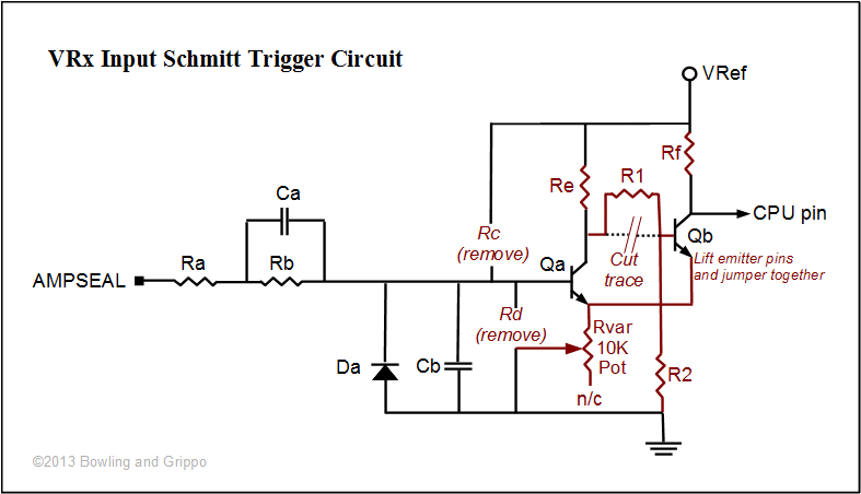
The VR circuit can be configured as a zero to five volt Schmitt trigger by removing two resistors (R44 & R45), changing the values of two other resistors (R42 & R43), and adding a jumper, two resistors (R1 & R2) and a potentiometer (Rvar):
- If you have already built the circuit and are retrofitting the Schmitt modifications, remove R44 (aka. Rc). Either desolder R44, or cut both leads and remove it. If you are building the circuit for the first time, leave the R44 location empty.
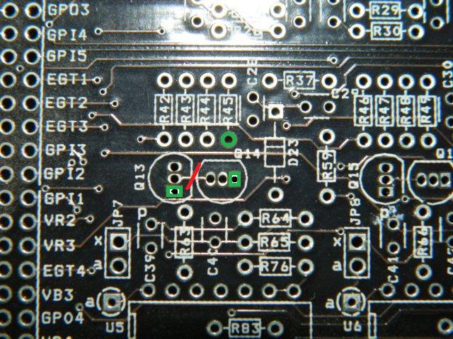
- If you have already built the circuit and are retrofitting the Schmitt modifications, remove R45 (Rd) Either desolder it, or cut both leads and remove it. If you are building the circuit for the first time, leave the R45 location empty. You might want to leave the lead that goes to ground (the end furthest from the heat sink - check with a meter for <1Ω to the ground pin on the voltage regulator (its center pin)) as long as you can, so that you have the option of soldering other components to ground more easily in later steps. Suitable grounds are marked in green in the photos below.
- The default value for R43 (aka. Re) is 33K Ohms, should be lowered to 10K Ohms from the default 33K Ohms. This sets the range of the hysteresis voltage with respect to the trigger voltage and pot resistance.
- If you are retrofitting the Schmitt circuit to a previously built VR circuit, you can solder a 10K resistor to the leads of the existing 33K resistor in R43 (i.e. in parallel), giving an effective resistance of 7674 Ohms = 1/((1/10K)+(1/33K)).
- If you are building the circuit for the first time, use a 10K resistor in the R43 location.
- The resistance value for R42 (Rf) should be lowered to 1K Ohms from the default 33K Ohms. This sets the trigger voltage with respect to the pot setting.
- If you are retrofitting the Schmitt circuit to a previously built VR circuit, you can solder a 1K resistor to the leads of the existing 33K resistor in R42 (i.e. in parallel), giving an effective resistance of 971 Ohms = 1/((1/1K)+(1/33K)).
- If you are building the circuit for the fist time, use a 1K resistor in the R43 location.
- You must cut a trace between the the base off Q13 (Qb) and the collector of Q14 (Qa). The trace is visible under the solder mask on the top side of the PCB (see the red cut line in the photo below).
Use a sharp razor knife (or Exacto® knife or equivalent) and firm pressure to cut a line perpendicular to the trace. You are not trying to cut the fiberglass substrate, you only need to cut through a few thousandths of an inch of copper, so you shouldn't need to go overboard. Use multi-meter to verify that there is no continuity (infinite resistance) between the two pin locations. Do worry that the cut seems very narrow; as long as there is no continuity, it will be fine.
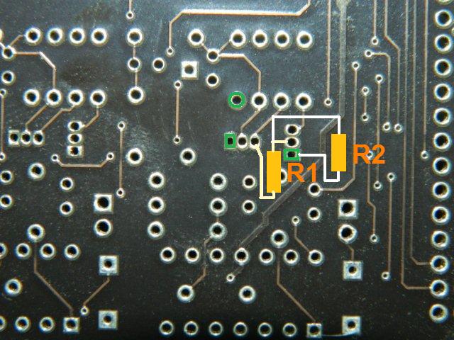
- You must solder a 1K Ohm resistor (R1) in place of the cut trace.
- You might find this easier to do on the underside of the board.
The resistor goes from the base of Q13 (its middle pin) to the collector of Q14 (the collector is the pin on the left when viewed so that the pins face away from you and the flat side of the transistor's plastic case is facing upwards). Unlike the emitter, the collector is not connected to ground, so check with a multimeter.
- Be sure to get the correct pins.
- Be very careful not to bridge the adjacent pins with solder or the jumper itself.
- If you are building the circuit for the first time, bend the emitter pins of the transistors up (see the next step), solder them in place, then add the resistor to the underside of the board before trimming the leads so you have the maximum length of pin to solder to.
There is a flat side and a rounded side on these transistors. The flat side of Q13 faces the Ampseal connector. The flat side of Q14 faces the heat sink. The pin spacing is very tight on these components, be sure not to bridge them with excess solder. If you do bridge them, use a solder wick to remove the excess solder. Make sure that Q14 does not touch the Zener diode in C40.
- One end of a second 1K Ohm resistor (R2) connects the base of Q13 to ground. The base is the middle pin. You can add this resistor by soldering to the end of the resistor R1 closest Q13 (on the bottom of the PCB), and the other end to either the empty transistor emitter pin location (with the square pad), or to the grounded end of R45 (that is not installed). Check for the grounded end with a multi-meter - there should be very little resistance <1Ω between the correct pad location and the center pin of the voltage regulator (U1).
- The Q14 (Qa) transistor and Q13 (Qb) transistor emitter pins must be lifted from the board and jumpered together, using a bit of lead snipped off a resistor (or equivalent).
- If you are building the circuit for the first time, bend the pins up before soldering the transistors in place.
- If you are retrofitting an already built circuit, it may be best to cut the pin with small side cutters as close to the PCB as you can, then bend the pin carefully upwards before soldering the jumper in place.
Use a hot soldering iron and the minimum time possible when soldering the jumper in pace to avoid heat damage the transistors.
- A variable resistor* (Rvar) connects from ground to the emitter pins lifted on the transistors (these pins are otherwise soldered directly to ground in the non-Schmitt trigger build). Using a 10K Ω pot as a variable resistor in this position allows the the trigger and hysteresis voltage levels to be adjusted together. The pot can be mounted to the case. Many pots, called panel-mount pots, have a threaded barrel and retaining nut that can be used to install the pot through a hole in the GPIO case's end-plate, allowing the VSS triggers to be adjusted externally on the fly. There are many such pots available from Digikey, Mouser, or even radio Shack or Frys. For an example, see part number 987-1318-ND ($1.02 ea.) from Digikey. However, be sure you have enough space to mount the pot you select. A smaller option is 53RAD-R16-B15L-ND.
- One of the pot's pins can be soldered to a lead which is then soldered to to the jumper added in the previous step between the transistor's emitter pins. (Which end pin in you choose will set which direction increases the resistance, and thus which way to turn the pot. You can check this with a multi-meter. Higher resistances will give higher trigger and hysteresis thresholds)
- The pots middle pins should be soldered to a lead which in turn is soldered to ground. The ground spot to run the lead to can be:
- the empty spot where the emitter pin would have gone (the square pin on either transistor's pads), or
- the grounded end of the resistor R45 (Rd) location (which will be empty if you are building for the first time, or have desoldered the resistor from a previous build).
- The final pot pin can be left un-connected.
* If you know the signal's characteristics, you can replace the pot with a fixed resistor Rvar. You can use the calculator below to determine the appropriate value (alternately, you can adjust the trigger and hysteresis values independently be using a fixed resistor for Rvar and substituting values for R43 and R42)
If you have built the circuit previously, you are done with the modifications. If you are building the circuit for the first time, there are a few more steps to complete:
- Install and solder a 10K Ohm, 1/4 Watt resistor {brown-black-orange, 10KQBK-ND} in R59 (Ra).
- Install and solder a 220K Ohm, 1/8 Watt resistor {red-red-yellow, 220KEBK-ND} in R37 (Rb).
- Install and solder a diode {1N4001DICT-ND} in D23 (Da) with the banded end closest the heat sink, as shown on the silkscreen.
- Install and solder a 47 pF capacitor {399-4300-ND} in C28 (Cb).
- Install and solder a 470 pF capacitor {399-4301-ND} in C29 (Ca). The label for C29 is partially obscured on silkscreen.
The Schmitt trigger circuit's voltage thresholds are:
- Vtrigger = Vsupply × (Rvar ÷ (Rvar + R43))
- Vhysteresis = Vsupply × (Rvar ÷ (Rvar + R42))
Here is a calculator to assist in determining appropriate values for your set-up.
For the other VR circuits on the GPIO PCB, the equivalent components are:
| Ra | Rb | Rc | Rd | Re | Rf | Qa | Qb | Ca | Cb | Da |
| VR1 | R59 | R37 | R44 | R45 | R43 | R42 | Q14 | Q13 | C29 | C28 | D23 |
| VR2 | R60 | R38 | R48 | R49 | R47 | R46 | Q16 | Q15 | C31 | C30 | D24 |
| VR3 | R61 | R39 | R52 | R53 | R51 | R50 | Q18 | Q17 | C33 | C32 | D25 |
| VR4 | R62 | R40 | R56 | R57 | R55 | R54 | Q20 | Q19 | C35 | C34 | D26 |
If none of the tips above help, and you are lucky enough to have an oscilloscope, and could get a trace of the VSS signal in action, that would be the best way to decide what to do next, of course. You would then know if the signal is high or low amplitude, if it coincided with anything the controller is doing, etc. Post your results and your MSQ settings file plus a datalog that illustrates the issue on the MShift™ forums, and we can provide some advice.
MegaSquirt® and MicroSquirt® controllers are experimental devices intended for educational purposes.
MegaSquirt® and MicroSquirt® controllers are not for sale or use on pollution controlled vehicles. Check the laws that apply in your locality to determine if using a MegaSquirt® or MicroSquirt® controller is legal for your application.
© 2012, 2015 Bruce Bowling and Al Grippo. All rights reserved. MegaSquirt® and MicroSquirt® are registered trademarks. This document is solely for the support of MegaSquirt® boards from Bowling and Grippo.