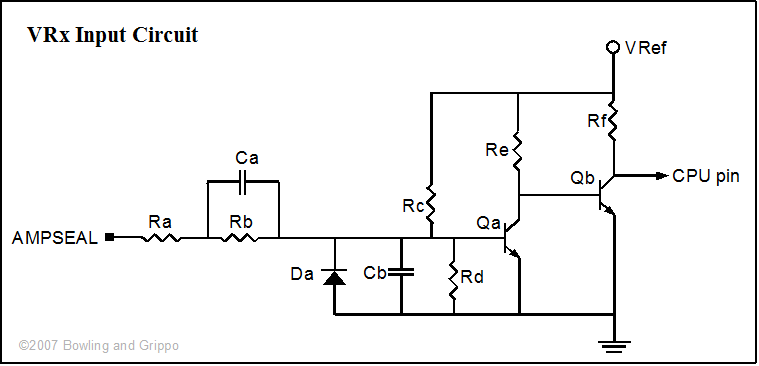
The GPIO board has four VR inputs based on discrete components.
Circuit | CPU Port | AMP pin number |
| VR1 | PT0 | 2 |
| VR2 | PT6 | 15 |
| VR3 | PT5 | 14 |
| VR4 | PT7 | 29 |
The variable reluctor circuits have only two transistors, a diode, two caps, and 6 resistors. One can view a grounded VR sensor the same as an unbalanced audio microphone, for which there are a ton of circuits like this one. This is a simple DC-coupled transistor amplifier circuit.
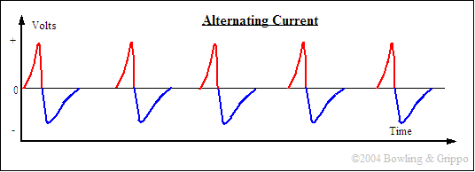
This circuit takes the signal from a variable reluctor (VR) sensor. The VR sensors have an alternating current (AC) signal that needs to be conditioned (transformed into a DC square wave) before it is suitable for the processor.

Here is a quick explanation of the VR circuit operation: the VR sensor feeds into Ra for attenuation, followed by Rb and the "speedup capacitor" Ca. Da prevents transistor damage from the negative VR signal cycle. Cb shunts real high frequency noise to ground.
Rc biases the base of the transistor, with the help of the 2 MegaOhm resistor (Rd) from base to +5V. Rc is a 2 MegaOhm resistor which forms a voltage divider circuit with Rb, Ra, and the VR sensor resistance. What this voltage divider does is bias the base of NPN transistor Qa somewhat.
Rd is the other leg of the voltage divider, it is a 300K ohm resistor. This works with the 2M resistor to make up a voltage divider. The junction point is roughly 0.6 volts = ( 5 volts * 300K/(2M + 300K) ). This brings the base voltage up to this level. The input VR voltage is basically added to this, it is in fact a DC bias. The transistor has a base-emitter voltage drop of 0.7 volts before it can conduct. So the divider helps overcome the voltage drop, otherwise the sensor itself would have to put out at least 0.7 volts before the transistor started conducting.
This is a standard bias arrangement used in all transistor amps, what it does is bias the base up from ground a bit, in this case roughly 0.6 volts. The Vbe drop is right around 0.7 volts, so this bias assists the VR sensor from having to overcome the Vbe drop. It's not enough to source current thru the B-E junction, this comes when the VR sensor generates a current in the positive direction (after it passes thru the series resistance Ra and Rb). With the recommended values, the VR sensor voltage trigger threshold (assuming no VR sensor impedance, which is not true) is right around 0.5 volts or so. There is a slight temperature coefficient effect here but this will only change things in the few millivolt range.
Qa amplifies the current which is direct-fed into Qb base. Note that Rd and Re also bias Qb but with much more steady-state current. Qb then further amplifies the signal and at this point the signal has a significant current gain. The output of Qb is pretty much a digital switch from 5V to 0.7 volts, this can be presented to a processor input capture port.
The rising edge is the intended trigger edge for this circuit. The other edge direction is not as clean.
Ca is known as a "speedup capacitor". What this does is help give an added boost to the base current during transitions in order to make the transistor turn on (and off) quicker. This is a trick used often in transistor pulse circuits. See this link for more info.
Absolutely nothing is critical for components in the VR circuit. The 2N3904 is specified, but virtually any NPN transistor will probably work, like a 2N2222.

The above schematic is general, the specific components on the boards that correspond for each VR circuit to each item in the schematic are:
| Ra | Rb | Rc | Rd | Re | Rf | Qa | Qb | Ca | Cb | Da | |
| VR1 | R59 | R37 | R44 | R45 | R43 | R42 | Q14 | Q13 | C29 | C28 | D23 |
| VR2 | R60 | R38 | R48 | R49 | R47 | R46 | Q16 | Q15 | C31 | C30 | D24 |
| VR3 | R61 | R39 | R52 | R53 | R51 | R50 | Q18 | Q17 | C33 | C32 | D25 |
| VR4 | R62 | R40 | R56 | R57 | R55 | R54 | Q20 | Q19 | C35 | C34 | D26 |
| Component | Default Values | Marking | Notes |
| Ra | 10 K | brown-black-orange | 1/2 Watt |
| Rb | 220 K | red-red-yellow | |
| Rc | 2 M | red-black-green | |
| Rd | 300 K | orange-black-yellow | |
| Re | 33 K | orange-orange-orange | |
| Rf | 33 K | orange-orange-orange | |
| Qa | 2N3904 | TO-92 package | |
| Qb | 2N3904 | TO-92 package | |
| Ca | 470 pF | ||
| Cb | 47 pF | ||
| Da | 1N4001 |
The VR sensor is an induction type sensor, it is "passive", i.e. it does not require a power source, and has a small magnet built in.
The sensor uses a magnetic pickup to produce a signal. A core of steel is wrapped with hundreds of turns of fine wire at one end. A small magnet is attached to the other end, and this assembly is mounted in the distributor facing the distributor shaft. When a notch, pin, teeth or hole in a timing wheel (the reluctor) moves past the sensor, it causes a change in the magnetic flux field around the sensor. As the teeth of the reluctor approach the coil assembly, the flux from the magnet is pulled in close to the bar. The sudden field change induces an electrical current in the coil, which is then converted to a voltage signal by electronic circuitry in MegaSquirt-II. As the teeth move away, the flux springs back outward, inducing a voltage in the pickup coil. This induced current has reversed direction as the magnetic field returns to normal.
The result is an alternating current (AC) voltage that reverses polarity and crosses zero as it the pin aligns with the sensor. The output voltage of this sensor varies with the speed of the engine. The VRx circuits convert these AC signals into 5 Volt digital signals, suitable for the processor.
VR sensors are used in a number of places in modern vehicles, such as some:
The variable reluctor sensor has been the most widely used in automotive ignitions. It has been used by virtually every auto manufacturer for many years and is still widely used. The GM high energy ignition (HEI) is one example. It is a rugged, reliable system that holds up well in a high temperature, high vibration environment. A variable reluctor magnetic sensor typically has two wires, and possibly a shield wire. Because it generates a signal without requiring external power, it is very easy to implement. The magnetic variable reluctor sensor is gradually being phased out in modern automobiles, however, because it has limited ability to sense teeth that are very close together, which is necessary to gain the positional accuracy required by modern engine management systems.
At low rotation speeds, the VR sensor's output is approximately 0.6 volts, at mid-RPM it is close to 3 volts, and at very high RPM it can go as high as ~50 volts. This type of sensor produces an alternating current (AC) wave output. The pulse is positive when the "pole", is approaching, and negative when the pole is leaving (if you have the right polarity). The simplest way to see this is by hooking it up to a cheap analog voltmeter and using a wrench or other "non magnetic - soft iron", piece of metal. When you place the metal piece on the sensor the needle on the voltmeter will swing one way. When you quickly remove it the needle will swing the other way.
A magnetic crank position sensor should also produce an alternating current when the engine is cranked so a voltage output check can be performed. With the sensor connected, the output voltage across the appropriate module terminals while cranking the engine should be at least 20 milliVolts (mV) on the AC scale of your meter. If this is the case, the sensor is probably good, meaning any fault is probably in the module.
The VR circuits can be configured a number of other ways besides being a zero-crossing detector circuit. For example, to build the circuit as a digital input, you could: