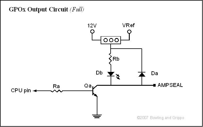
In addition to dedicated pulse width modulation and high current ignition driver outputs (and a variety of input circuits), the General Purpose I/O (GPIO) board has four general purpose output circuits. These can be configured by the builder to operate as grounding circuits (with or without flyback), light emitting diode drivers, grounding circuits with 'pull-up' voltage. Clever users can find other ways to configure these output circuits, of course.

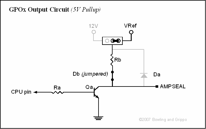
The above schematic is general, the specific components on the boards that correspond for each GPO circuit to each item in the schematic are:
| Ra | Rb | Da | Db | Qa | Jumper | |
| GPO1 | R13 | R14 | D15 | D19 | Q9 | JP1 |
| GPO2 | R17 | R18 | D17 | D21 | Q11 | JP3 |
| GPO3 | R15 | R16 | D16 | D20 | Q10 | JP2 |
| GPO4 | R19 | R20 | D18 | D22 | Q12 | JP4 |
The individual GPOx circuits connect to the ampseal connector and processor as follows:
Circuit | CPU Port | AMP pin number |
| GPO1 | PM4 | 10 |
| GPO2 | PM3 | 7 |
| GPO3 | PM5 | 8 |
| GPO4 | PB4 | 9 |
Any of the output circuits can be configured in any way: they don't all have to be the same, and not all have to be installed.
The default transistor for the GPOx circuits is the ZTX450. This transistor is capable of a continuous current of up to 1 Amp. Larger capacity transistors can be used, such as the ZTX651 (NPN, 2 Amps continuous current), however the current may ultimately be limited by the ability of the board's traces to carry the required current (they are designed for up to 2 Amps continuous current).
This circuit consists of:
| ID | Default Value | Install? | Notes |
| Q1 | yes | transistor, see below for advice on selecting an appropriate transistor and base resistor. | |
| R1 | yes | base resistor, see below for advice on selecting an appropriate transistor and base resistor. | |
| R2 | no | not used | |
| D1 | no | not used | |
| D1 | no | not used | |
| J1 | no | not used |
This circuit simply grounds a device through a transistor when commanded by the processor. It is suitable for low current devices that provide a voltage signal which can be 'pulled low', such as some ignition modules, external LEDs, etc. Note that the circuit has two states: grounded (active), and floating (inactive). See below for advice on selecting an appropriate transistor and base resistor. If you need a 5 or 12 Volt signal that switches from high to low (5 or 12 Volts to ground), use the pull-up circuit instead.
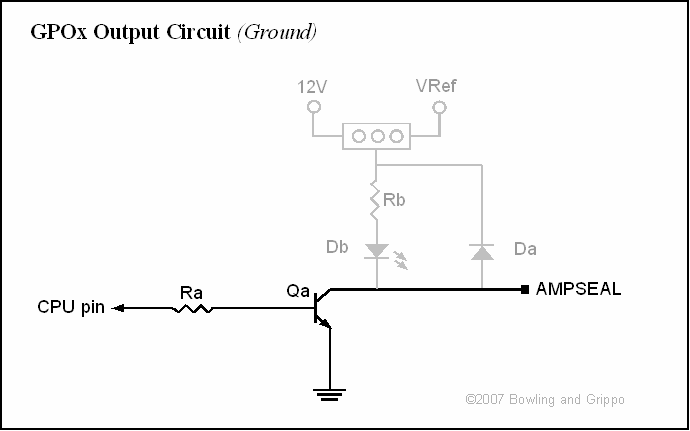
This circuit consists of:
| ID | Default Value | Install? | Notes |
| Q1 | yes | transistor, see below for advice on selecting an appropriate transistor and base resistor. | |
| R1 | yes | base resistor, see below for advice on selecting an appropriate transistor and base resistor. | |
| D1 | yes | flyback diode | |
| J1 | yes | jumper | |
| R2 | no | not used | |
| D1 | no | not used |
The flyback ground circuit is used for connecting devices that have moderately high inductance, typically a relay or solenoid. 12 Volts is supplied to the relay/solenoid, and it is grounds through the GPIO flyback ground circuit. These devices create a flyback voltage spike when the current is stopped, and in this circuit, this voltage spike is passed to the 12 Volt supply through the flyback diode (D1), reducing the potential for damage to the transistor. (Note that if your device is powered by a 5 Volt supply, you should jumper J1 to the 5 volt supply.)
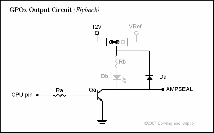
This circuit consists of:
| ID | Default Value | Install? | Notes |
| Qa | yes | transistor, see below for advice on selecting an appropriate transistor and base resistor. | |
| Ra | yes | base resistor, see below for advice on selecting an appropriate transistor and base resistor. | |
| Rb | yes | current limiting resistor for the LED | |
| Db | yes | light emitting diode | |
| J1 | yes | jumper | |
| Da | no | not used |
This circuit is used to operate a light emitting diode (LED). There are no external connections, however the LED can be moved off the board simply by extending the leads to the LED with wires. See below for advice on selecting an appropriate transistor and base resistor.
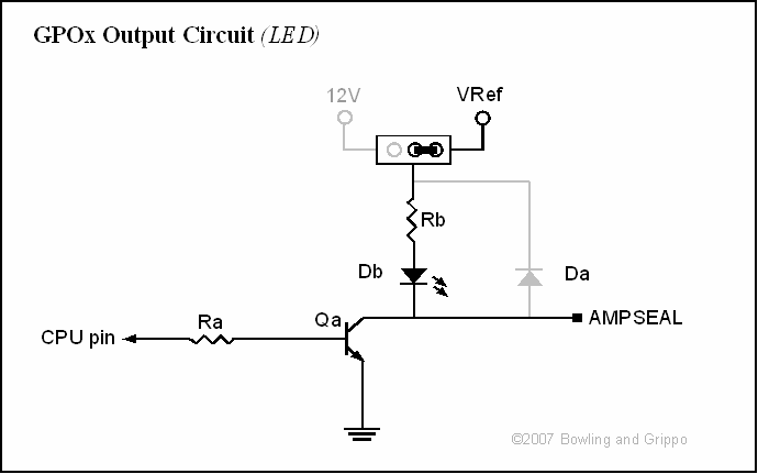
This circuit consists of:
| ID | Default Value | Install? | Notes |
| Qa | yes | transistor, see below for advice on selecting an appropriate transistor and base resistor. | |
| Ra | yes | base resistor, see below for advice on selecting an appropriate transistor and base resistor. | |
| Rb | yes | current limiting resistor for the LED | |
| J1 | yes | jumper | |
| Da | no | not used | |
| Db | no | not used |
The pull-up circuit is used to provide a 5 or 12 Volt signal that switches from high to low (5 or 12 Volts to ground). This is used for things like some ignition modules, and for connecting to some other electronic devices. See below for advice on selecting an appropriate transistor and base resistor.
Choosing a Transistor for an Output Circuit
The GPIO general purpose output circuits are set up for NPN transistor in a TO-92 package.
A transistor has three connections:
Note that this means that the transistor can do two things:
In most cases, the GPOx circuit will be used to switch external devices. To select a transistor for this purpose:
Ic = Vs/R (this is Ohm's Law - the most fundamental relationship of electrical circuits)
Typically, for external automotive devices, the supply voltage is ~12V.
For example, suppose our device has a measured resistance of 48 Ohms. The Ic = 12/48 = 0.250 Amps = 250 milliAmps
hFE(min) > 5 × (load current Ic / max. chip current)
For the 9S12 processor on the GPIO board, the absolute maximum output current is 25 milliAmps, and it's better to keep it to 10 milliAmps. So you would need:
hFE(min) > 5 × (load current Ic / max. chip current) = 5 * ([Vs/r])/(.010) = 500 * [Vs/R]
For a 12 Volt supply, this works out to approximately:
hFE(min) > 500 * [Vs/R] = 6000/R
With our previous example, this works out to:
hFE(min) > 6000/R = 6000/48 = 125, so hFE must be at least 125
| Common Name | Ic | hFE | Digi-Key Part Number | |
| -ND | ||||
| -ND |
Rbase = (Vc × hFE) / (5 × Ic)
where
Vc = chip supply voltage (5.0 for the 9S12)
So from our previous example:
Rbase = Ra = (Vc × hFE) / (5 × Ic) = (5.0 x 125) / (5 * .250) = 125/.250 = 500 Ohms
For our example, if you calculate 500 Ohms for the base resistor, use the 470 Ohm resistor (1/8 watt is fine for the base resistors likely to be used on the GPIO board).
Finally, remember that if the load is a relay or solenoid, you must use the flyback circuit, which has a protection diode (Da).
By the way, a Darlington transistor is two transistors packaged together to give a very high current gain (hFe). The current amplified by the first is amplified further by the second transistor. The overall current gain, hFE, is equal to the two individual gains multiplied together. As a result, hFE > 10000 isn't unusual, and these are suitable for controlling larger currents using the processor port.
Choosing a Light Emitting Diode for an Output Circuit
Light emitting diodes do two things:
The light emitting property allows us to use LEDs as indicators, controlled by the CPU (and a transistor).
The LED hole spacing on the GPIO board is for T3/4 LEDs (this is the package size that defines the physical dimensions of the LED). You may be able to use other LEDs by bending and/or jumpering leads.
The resistor value, Rb on the GPOx circuits, can be calculated as:
Rb = (Vs - Vl) / I
where
For example, on the GPIO board, the supply voltage Vs = 5V (unless you have jumpered to the 12V supply), for a red LED (Vl = 2V), requiring a current I = 20mA = 0.020A, you would use:
Rb = (5 - 2) / 0.020 = 150 Ohms
You can use higher resistances to dim the LED, or to reduce the current draw.
Choosing a Flyback Diode for an Output Circuit
The flyback diode has two important parameters:
The GPIO board is set up for diodes in a DO-41 package. These have a body that is approximately 4 mm to 5mm long and 2.0 to 2.7 mm in diameter, with axial leads (that are 0.7 to 0.9 mm in thickness). Other diodes can sometimes be used by bending leads, etc.
The 1N4001-1N4007 series of diodes are very common. They have a reverse voltage rating of at least 50 Volts (1N4001), all the way up to 1000 Volts (1N4007). Their surge current can be up to 30 Amps. Any of them is suitable for the flyback diode.
Choosing a Pull-Up Resistor for an Output Circuit
The pull-up resistor is used to limit the current flow from the pull-up voltage source when the transistor (Qa) is grounding the circuit. When the transistor is 'open' (i.e., not allowing current to flow), the pull-up voltage will be applied to the circuit, as long as the external device is not grounded (is very high impedance). So the pull-up resistor can be relatively high resistance, limiting the current draw.
I = Vs/Rb (Ohm's Law applied to the pull-up circuit)
(ignoring the voltage drop in the transistor)
For example, if Vs = 12 V, and we have a pull-up resistor of 1K Ohms (1000 Ohms), then:
I = 12/1000 = .012 Amps
P = I * Vs, in Watts
and since V = 1/Rb, P = I2/Rb as well
So in our example:
P = 0.012*12 = 0.144 Watt
Since this is more than 1/8 Watt (0.125 W), we should use a 1/4 Watt resistor for continuous duty. However, if the external device is not ON for long periods, but instead is switched regularly, it may be possible to use a 1/8 Watt resistor. Different physical size resistors can be installed by bending the leads appropriately.