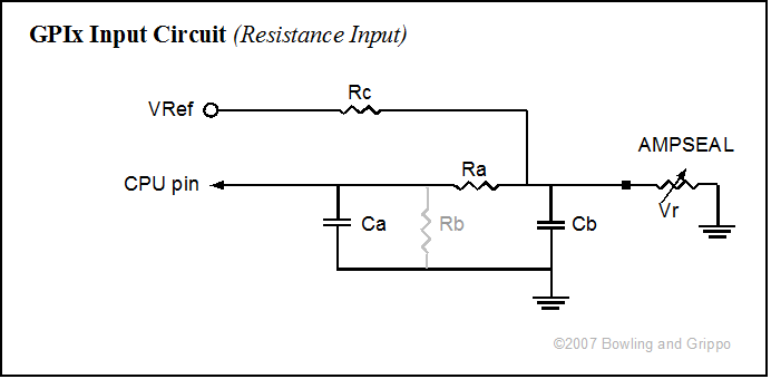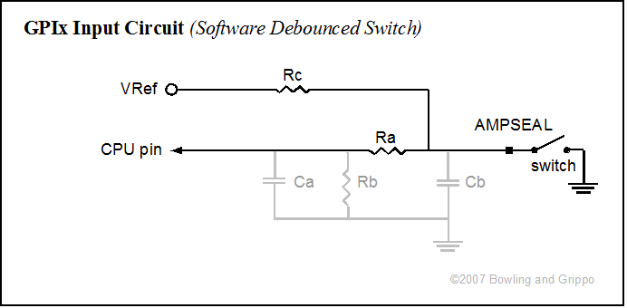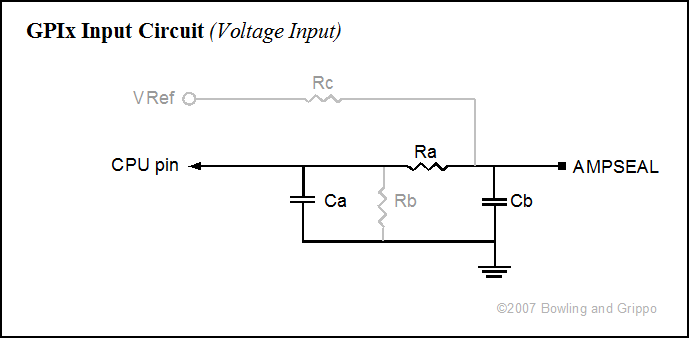
In addition to dedicated variable reluctor (VR) and exhaust gas temperature (EGT) inputs (and a variety of output circuits), the General Purpose I/O (GPIO) board has five general purpose input circuits. These can be configured by the builder to operate as voltage sensing circuits, resistances sensing circuits, or hardware-debounced switch input circuits. Clever users can find other ways to configure these input circuits, of course.
Circuit | CPU Port | AMP pin number |
| GPI1 | PAD00 | 5 |
| GPI2 | PAD01 | 6 |
| GPI3 | PAD02 | 30 |
| GPI4 | PAD07 | 3 |
| GPI5 | PAD06 | 4 |
Any of the input circuits can be configured in any way, they don't all have to be the same, and not all have to be installed.
The full general purpose input circuit looks like this:

| Ra | Rb | Rc | Ca | Cb | |
| GPI1 | R27 | R28 | R21 | C14 | C15 |
| GPI2 | R29 | R30 | R22 | C16 | C17 |
| GPI3 | R32 | R31 | R23 | C18 | C19 |
| GPI4 | R33 | R34 | R24 | C20 | C21 |
| GPI5 | R35 | R36 | R25 | C22 | C23 |
However, to make it a voltage, resistance or switch sensing circuit, you will install only some of the components.

This circuit acts like a voltage divider. The supply voltage (5.0 Volts) is dropped to zero (ground) through Rc (the "bias resistor") and the variable resistance (Rv) itself. The output voltage to the processor is taken from between Rc and Rv. This output voltage signal would usually be fed to a analog-digital converter (ADC) pin on the processor (PAD00 to PAD07). It varies from 0 to 5 volts by the function:
Normally we want the middle of the ADC voltage range (i.e., 2.5 Volts) to correspond roughly to the middle of the sensors most widely used range.
For example, with a GM temperature sensor, the resistance at 80°F is about 2500 Ohms, so2.5 = 5.0 * [(2500)/(Rc + 2500)]
(2.5/5.0)/2500 = 1/(Rc + 2500)
or
Rc = 3400/(2.5/5.0) - 2500 = 2500
This explains why the standard MegaSquirt® configuration for GM temperature sensors uses a 2.49K Ohm resistor.
Software De-Bounced Digital Input Circuit

For a software de-bounced GPIx circuit with a 5 Volt signal (some Hall sensors, switches used to ground the pin, etc.), you can do this simply by installing Rc and putting a 1K Ohms resistor the Ra location, and leaving out all the other components. For the GPOx circuit, you would leave out all the components, and jumper 'a' to 'p' (don't forget to set the port as an input). The other inputs/outputs can be jumpered similarly.
The resistor Rc limits the current flow when the switch is closed. Generally, you want to keep this to about 10 to 25 milliAmps, so a value of:
Rc = Vsupply/I = 5.0/0.015 = 330 Ohms should work well.
Some users may want to de-bounce in hardware. This can be done, but requires a Schmitt trigger in addition to other components. Some of these can be installed in the existing locations, but some would have to be installed in the proto area.
For nominal 12 Volt digital inputs (some Hall sensors, brake inputs and the like), the user will need to bring the signal voltage 'high' down to 5 Volts. To do this, you can create a voltage divider by using Ra = 2 × Rb, then putting a 5.1 Volt Zener diode in place of Ca, with the banded end towards the processor (unbanded end to ground).
The resistors lower the voltage to 32% of the signal value (4.64 Volts on a 14.5 Volt input), and the Zener diode ensures the resulting voltage doesn't exceed the port's maximum (i.e., if the vehicle's voltage regulator fails, the tolerances of the resistors are way off, etc.). The processor will see any Voltage between 0 and 1.75 Volts as a 'low', any Voltage between 3.25 and 5.0 as 'high' and anything in the range of 1.76 to 3.24 as indeterminate (the input current will only be about 2.5 µAmps).
Typical values for a 12V input signal are Ra = 1000 Ω, Rb = 470 Ω, Zener diode = 1N4733ADICT-ND at Digi-Key. You can use a 'smoothing' capacitor at Cb, if you need/wish to. There is more on this in the 'voltage sensing circuit' section below.
Note if you use the microcontroller's internal pull-up by setting it in the code with the pull up enable register(s), and do not use the external pull up through Rc, then you must also jumper Ra. This is because the pull up voltage must be 'downstream' of any resistances on the path to the processor (otherwise the resistance Ra would drop the pull up voltage, and the processor pin would always be high on the processor side of Ra). If you do use the internal pull-up, you can still use the external pull-up (5V through Rc and still use Ra), as long as it is the same voltage (5V) as the internal pull-up.

This circuit is the equivalent of the MegaSquirt® TPS voltage sensing circuit. It works well for voltages that transition smoothly, and that DO NOT exceed 5 Volts maximum at any time.
In the 5V voltage sensing configuration, Ra merely limits any possible current to the processor pin (there would normally be very little current anyhow). It can only be used if the processor pull-up voltage is not used. With an external pull-up (from Vref, for example), 1K Ohms is fine for the Ra resistor.
If you are sensing a signal with a nominal 12V amplitude, then you need to make a voltage divider from Ra and Rb. To do this, you can create a voltage divider by using Ra = 2 × Rb (Ra = 1K Ohms and Rb = 470 Ohms works, as do many other combinations), then putting a 5.1 Volt Zener diode in place of Ca, with the banded end towards the processor (unbanded end to ground).
Note that Rb is not normally installed in the 5V configuration. However, in some cases where the voltage swings rapidly, installing a 1M Ohm resistor in the Rb location and leaving Ca out is preferable (this creates the equivalent of the MegaSquirt® EGO input circuit). If the supply voltage is 5V, you don't need the voltage divider, and you can replace Rb with a 5.1 Volt Zener diode to protect processor port from voltage spike (non-banded end goes to ground).
Do not install Rc (the pull-up circuit resistor).
Omit Ca.
Cb is purely for noise filtering. The spec is 0.1 to 1.0 µF, and Cb can also be left out completely if the signal is reasonably smooth.
This circuit's output voltage signal would usually be fed to a analog-digital converter (ADC) pin on the processor (PAD00 to PAD07).
Note that if you wish to measure voltages greater than 5 volts, you must create a voltage divider. You do this by install an appropriate resistor in Rb (as noted above in the digital input section). The voltage signal at the CPU is then:
For example, if you have a nominal 12 Volt signal (up to 15 Volts in practice), then since we want Vout to be no more than 5 Volts when Vsignal = 15, we calculate:5.0 = 15.0 * [(Rb)/(Ra + Rb)]
If Ra is 2.0K Ohms, then:
Rb = (5.0/15.0) * (Ra + Rb) = 1/3*Ra + 1/3*Rb
=> 2/3*Rb = 1/3*Ra
=> Rb = Ra/2 = 1.0K Ohms
and the current draw on the signal source is:
I = Vsignal/(Ra + Rb)) = 15.0/(1.0K + 2.0K) = 5 milliAmps, which is minimal
This would be good values for a stop lamp switch input, for example.
The voltage divider method above works well if the signal voltage is known and not prone to spikes. However, it does have the disadvantage of the output voltage being a function of the input voltage. Where there are spikes in the supply, or where a more certain ON/OFF voltage is needed, or the processor port needs protection from over-voltages, a Zener diode can be used instead (in the place of C1).
A Zener diode flows current in one direction, but only flows in the other direction above a certain specified voltage. The Zener diode reverse voltage can be chosen to be 4.9 Volts, and used to shunt the signal to ground. This gives the processor 4.9 Volts whenever the signal voltage is greater than or equal to 4.9 Volts. A current limiting resistor (Ra) must be used to prevent the diode from overheating.
The power dissipated by the diode will be:
P = I * VZener, in Watts
So for a typical 1.0 watt diode, with a 15 Volt supply:P = 1.0 = I * 4.9, so the current (I) must be less than 1.0/4.9 = 204 milliAmps
This means the current limiting resistor Rb needs to be at least:
R = (Vsignal - VZener)/I = (15 - 4.9)/.204 = 50 Ohms
For maximum life, however, we would want to dissipate much less than 1.0 Watts in the diode, so lets choose 0.10 Watts instead. Then:
P = 0.10 = I * 4.9, so the current (I) must be less than 0.1/4.9 = 20 milliAmps
This means the resistor Rb needs to be at least:
R = (Vsignal - VZener)/I = (15 - 4.9)/.020 = 500 Ohms (this is Ohms Law rearranged slightly)
A 560 Ohm resistor should be fine in this case. Note that we do not want to make the current limiting resistor so high that no signal is transmitted, though this isn't generally a problem for most processor port inputs, and values up to 1K Ohm are generally okay.