CANbus Pass-Through
CANbus pass-through is a system that allows one laptop running TunerStudio to set the parameters and datalog more than one controller at a time (as long as the controllers are CANbus connected).
The CANbus pass-through is tested and works with B&G code versions:
These codes work with TunerStudioMS only (0.999.8c or higher). There are two reasons:
- TunerStudioMS has the full CANbus pass-through infrastructure to work with the new capabilities of the code,
- TunerStudioMS has the MAF table burning ability that these codes employ (and that MegaTune can't handle).
Older codes may work partially with the CANbus pass-through. For example, with the appropriate INI mods (see the CAN_COMMANDS sections of the INIs for the codes above to see how this might be done) older codes may allow variable display and datalogging, but not editing of parameters.
You need to set up for the CANbus pass-through under TunerStudio 'File/Project Properties/CAN Devices'. If your MS-II™ is the primary controller (the one you will connect the PC to) in the project, DO NOT set it up as a CANbus device. Only set up the GPIO board as a CANbus device. The primary project controller will always use the CANbus ID as defined in the ini (normally 0).
The CANbus physical connections are:
- CANH to CANH,
- CANL to CANL.
The termination resistor is already installed on the MS-II board. The termination resistor on the GPIO is R82 (120 Ohm, ¼ Watt resistor).
On MS-II™ controllers, the CANbus circuits are:
- CANH: CPU pin PM0 (#45) → 40-pin socket pin 6 → JS6 jumper to SPR1/CANH → DB37 pin 3,
- CANL: CPU pin PM1 (#44) → 40-pin socket pin 11 → JS8 jumper to SPR2/CANL → DB37 pin 4.
On the GPIO, the connections are:
- CANH: Ampseal connector pin 13,
- CANL: Ampseal connector pin 16.
To set up TunerStudio to use MShift™ with CANbus from MS-II™:
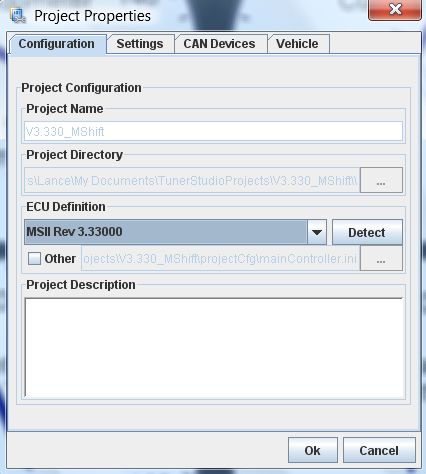
- First set the MS-II™ up normally under the 'File → Project → Project Properties → Configuration' tab (if you haven't already set up a controller for your engine controller):
- Give your project a name and description,
- Select the INI to match the firmware on your primary controller (MS-II™, MicroSquirt®, Sequencer™, etc.). You can either:
- use a 'pre-defined' firmware from the drop-down list, or
- click 'Other' and browse to a specific INI file.
- Click "OK".
TunerStudio will make a copy of the INI you navigated to, and put it in the ProjectCfg subfolder under the name "mainController.ini"
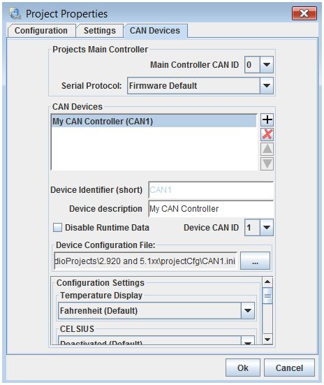
- Then set up the MShift™ GPIO controller under the 'File → Project → Project Properties → CAN Devices' tab of the engine controller project:
For example, if you have a Project that has an MS-II™ as the main controller you will connect the laptop to, and a GPIO board with MShift™ as a CANbus device with the CAN ID set to 1 (the default), only GPIO board goes in CAN Devices list and the CAN ID should be set to 1.
- In the 'Projects Main Controller' section:
- Main Controller CAN ID (i.e. engine controller CAN ID) should normally be 0.
- Serial Protocol should normally be the Firmware Default.
- In the 'CAN Devices' section:
- Device Identifier (short): Give your CANbus controller a short name. This will preface the menu entries as they drop down in TunerStudio so you always know which controller you are working with when you change parameters in the menus. The default is 'CAN1'.
- Device description: This is a longer description to remind you of the configuration you are setting.
- Device CAN ID: The CAN ID for the MShift™ code has a default value of 1. Use the value of 1 unless you have changed the value in the MShift™ firmware.
You can change the CAN ID in the menus to a value up to 13 to avoid conflicts with other CANbus devices - if you do change the MShift™ CAN ID you must also change it to the same new value under 'File/Project Properties/CAN Devices'.
- Device Configuration File: You will have to set the 'Device Configuration File' to point the GPIO_MShift_xxxx.ini file for your particular MShift™ code. Download the appropriate INI file, and then navigate to it in the CAN Devices setup menu in TunerStudio. The INI version must match the MShift™ code version you have loaded on your GPIO controller.
TunerStudio will make a copy of the INI you navigated to, and put it in the ProjectCfg subfolder under the name 'CAN1.ini'
Note that you can select another INI file at any time to update the INI (re-start TunerStudioMS to see the new INI), you don't have to remove the CANbus Device and then re-create it. If You are updating both the code and the INI, then you also have to reload the code on the MShift™ GPIO board using its serial connection, of course.
- Configuration Settings: Be sure to 'Activate' CAN_COMMANDS in the 'Configuration Setting' section of the CAN Devices dialog. This activates the use of CANbus pass-through mode for TunerStudio.
Here is a video on setting up CANbus in TunerStudioMS: CAN set-up video (22 MBytes)
Once set up for any CANbus devices, TunerStudio will replace the CAN ID in all the INI commands with the ID you set for the device in the 'File/Project Properties/CAN Device'. All of the menus for both MS-II™ and MShift™ will appear in TunerStudio (prefaced by the short Device Identifier).
In the tuning software, you may need to change some of the CANbus configuration variables if you are using 'non-standard' code. Find out more on how to do this here: www.msgpio.com/manuals/mshift/V22tune.html
CANbus Outmsg's
TunerStudioMS has the ability to burn new outmsg formats to the MegaSquirt® controller to allow it to pass different information to various CANbus devices. This function is under menu item 'Tools/Configure CANbus Outmsg'.
The formats are defined in a file called canOutmsg.inc, here is an example: canOutmsg.inc. This file should be placed in the Project folder \inc\ sub-directory.
The file format for the default CANbus outmsg is:
; CAN Outmsg
  DW  0              ; xrate, .128 tics
  DW  156            ; lsb
  DW  18             ; no_bytes (0-255)
  DW  19             ; dest id = 1 << 4 + varblk = 3
  DW  6              ; rpm offset (2 bytes)
  DW  7
  DW  8              ; adv offset (2 bytes)
  DW  9
  DW  18             ; map offset (2 bytes)
  DW  19
  DW  20             ; mat offset (2 bytes)
  DW  21
  DW  22             ; clt offset (2 bytes)
  DW  23
  DW  24             ; tps offset (2 bytes)
  DW  25
  DW  28             ; afr1 offset (2 bytes)
  DW  29
  DW  32             ; knock offset (2 bytes)
  DW  33
  DW  64             ; maf offset (2 bytes)
  DW  65
  DW  0	             ; nothing
  DW  0	             ; nothing
  ...
Where the variables are grabbed from the Outpc structure (look at the [OutputChannels] section of your code's INI for a complete listing) at the offsets listed (6,7,8, ... 32,33,64 & 65).
- The first line is a comment to identify the file and make any notes.
- The second line and third lines (DW 0 & DW 156 = 0*256 + 156 = 156) are the transmit rate. 0 means the message is only transmitted when requested, otherwise it indicates the clock speed in 0.128 tics at which a CANbus message will be transmitted automatically after receiving a request for data.
- The fourth line (DW 18) contains the total number of bytes to be transferred. This excludes the xrate, no_bytes and destination ID. Must be <= size of outpc and <= 255.
- The fifth line specifies the destination table ID (i.e., in which table the receiving CANbus device stores the received values). You must specify a value that is 16 more than the actual table ID, so 19 indicates table 3, 25 indicates table 9.
The transmitting and receiving controller must have the same outmsg structures, and they can have up to 8 of them on each controller.
MegaSquirt® and MicroSquirt® controllers are experimental devices intended for educational purposes.
MegaSquirt® and MicroSquirt® controllers are not for sale or use on pollution controlled vehicles. Check the laws that apply in your locality to determine if using a MegaSquirt® or MicroSquirt® controller is legal for your application.
© 2010, 2015 Bruce Bowling and Al Grippo. All rights reserved.