MegaShift™ and the GM Digital Ratio Adapter Controller (DRAC)
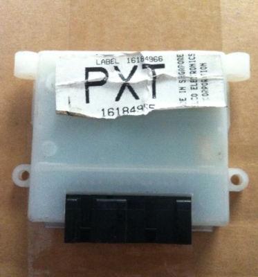
The Digital Ratio Adapter Controller (aka. DRAC, and similar to the Vehicle Speed Sensor Buffer - VSSB) found in many General Motors vehicles from 1992+ are a good solution for obtaining a clean 5 Volt square wave signal from a VSS sensor in a noisy environment. The DRAC is contained in a small white plastic case. It is typically bolted to the ECM or located directly behind the glove box.
In its OEM application, the DRAC typically sends:
These frequencies are derived from the VSS input frequency, so a specific calibration is required for a given tire diameter and axle ratio. This calibration is accomplished at the factory by soldering in selected jumpers on the DRAC's printed circuit board.
In addition to providing a clean square wave output of a few specific pulse/mile rates, a DRAC can also slow the signal frequency considerably, reducing the interrupt overhead in the code compared to handling the VSS signal directly.
There is more information on these DRAC modules here: 614streets.com/drac.html and in this PDF: DRAC.pdf
A DRAC will usually have two connectors. The smaller one may have the cruise control signal on pin 4 of the 4 pin connector (the other three pins are unused).
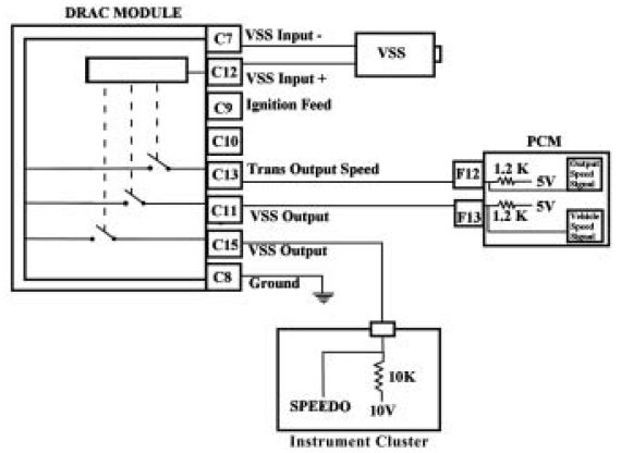
Typically the pins on the large connector are:
A switched 12V source is supplied to pin 9 to power the DRAC, and you should ensure you have a very good connection to ground on pin 8.
The VSS sensor connects to pins 7 and 12 (in some DRAC modules, at least - apparently there are at least a few connector variations - check the factory service manual for your DRAC to be sure). In GM applications, the 4L60e transmission used with the DRAC has 40 teeth on the output shaft for the VR sensor to sense.
There are up to six possible speed output pins:
Pin | Output | OEM Pull-up | Used by | OEM Output Frequency |
| 4 | VSS Output to Cruise Control | 5V pull-up through 1.2K resistor | Cruise Control | 4000 ppm Reduced frequency compared to VSS |
| 10 | VSS Output to RWAL (Rear Wheel Anti-Lock) | 5V pull-up through 1.2K resistor | ABS Module | 128000 ppm Increased frequency compared to VSS |
| 11 | VSS Output to ECM | 5V pull-up through 1.2K resistor | ECM | 2000 ppm Reduced frequency compared to VSS |
| 13 | Trans speed output (aka. "Output Speed") | 5V pull-up through 1.2K resistor | ECM | Similar frequency to VSS, possibly used with manual transmissions |
| 15 (and sometimes 14, esp. M & G vans) | VSS Output to instrument cluster (aka. "Speedometer Signal") | 10V pull-up through 10K resistor | Speedometer | 2000 ppm Reduced frequency compared to VSS |
The DRAC output is an 'open collector' output, so it needs a pull-up circuit to generate a voltage signal. This is accomplished through a current-limiting resistor connected a 5V voltage source, such as Vref (you can use 5V even on pin 15). The resistance value of the current limiting resistor isn't critical (it can be anywhere in the range from 1K Ohm to 10K Ohm).
The VSS output to the ECM on pin 11 is the best to use as it has a much reduced frequency compared to the VSS signal. However, this reduced frequency also means that you'll have to experiment with the VSS set up parameters (number of teeth, final drive ratio, tire size, etc.) in TunerStudio to get the correct speed reading. These don't have to match your actual tire size, etc.; but they must be used to get your speedometer to read correctly in TunerStudio. For example, some possible settings that might work:
If you were to use pin 13 for the speed signal, then the standard VSS setup (tire diameter, axle ratio, etc.) should work for you once you enter your number of teeth, final drive ratio, tire size, etc. (at the cost of a higher interrupt overhead).
The VSS output to the instrument cluster on pin 15 is another potential output to use, as it is also at a reduced frequency (though not quite as low as the signal to the ECM). You'll have to experiment with the VSS set up parameters to get the right speed reading in TunerStudio. While the specs call for a 10K Ohm pull-up to a 10V source for OEM use, you can safely use a 1K to 10K pull-up to 5V with the GPIO input.
With a DRAC, you should have a clean 5V square wave signal, so you no longer want a 'zero-crossing detector' circuit on your GPIO board (which could trigger on noise during the signal's 'low'). Instead you want to capture an edge where the signal is rising (or falling). In practice, that means detecting a voltage higher than zero volts but lower than 5V. So you will want to increase the trigger threshold voltage a bit. The best way to do this is to lower the resistance of the resistor in R45 (for VSS on VR1). The specified value is 300K Ohms, and you can try from 47K to 220K to eliminate the false triggering on a noisy signal (the lower the resistance, the higher the trigger voltage).