The GPIO board has four circuits intended specialized for exhaust gas temperature (EGT) measurements with K-type thermocouples. These can be used to measure four different cylinder's exhaust gas temperatures, or four points along the exhaust stream (such as pre/post turbine on a turbocharged engine).
Note that the EGT circuits can be used as general purpose inputs for resistance measurements (such as temperature senders) or voltage measurements (such as TPS) as well. Click here to find out more.
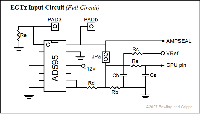
The above schematic is general, the specific components on the boards that correspond for each EGT circuit to each item in the schematic are:
| Ra | Rb | Rc | Rd | Re | Ca | Cb | PADa | PADb | JPa | |
| EGT1 | R73 | R74 | R86 | R79 | R72 | C45 | C46 | PAD12 | PAD8 | JP10 |
| EGT2 | R64 | R65 | R83 | R76 | R63 | C39 | C40 | PAD9 | PAD5 | JP7 |
| EGT3 | R67 | R68 | R84 | R77 | R66 | C41 | C42 | PAD10 | PAD6 | JP8 |
| EGT4 | R70 | R71 | R85 | R78 | R69 | C43 | C44 | PAD11 | PAD7 | JP9 |
Exhaust Gas Temperature Measurement
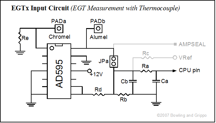
The EGT circuit by amplifying and correcting the small voltage output of a junction of dissimilar metals (called a "thermocouple") in the hot gas stream, creating a 0 to 5 Volt signal for the processor input port. This output voltage signal would usually be fed to a analog-digital converter (ADC) pin on the processor (PAD00 to PAD07).
Circuit | CPU Port | AMP pin number |
| EGT1 | PAD05 | 24 |
| EGT2 | PAD04 | 27 |
| EGT3 | PAD03 | 25 |
| EGT4 | PE1 | 26 |
Note that there are eight analog-digital converter (ADC) ports (PAD00-PAD07). These are capable of converting variable voltage into digital signals for measurement, such as for temperature sensors, exhaust gas oxygen sensors, and exhaust gas temperature measurements, etc. However there are nine potential circuits to use these ADC ports: 5 general purpose inputs, and 4 exhaust gas temperature circuits. As a result EGT4 is aligned with a non-ADC port (PE1). In order to use all four EGT circuits, this circuit should be reassigned to one of the PAD0x ports with an appropriate jumper, meaning one of the general purpose input (GPIx) circuits will need to be used for some other than an ADC port (voltage/resistance measurement). If the particular GPIx input is digital (on/off), the GPI port can be wired to PE1, for example.
The GPIO board is set up to use the common K-Type thermocouple. The K-type thermocouple is the 'general purpose' thermocouple. It is low cost and it is available in a wide variety of probes. Thermocouples are available in the 95°C to 1260°C (200°F - 2300°F) range. For example, a K type thermocouple (which is made of a nickel-chromium/nickel-aluminum junction, called Chromel-Alumel) puts out a signal of 12.2 milliVolts at 300°C. Sensitivity is approx 41 µV/°C.
In particular, Chromel-Alumel makes a thermocouple that will withstand up to 2500°F (just a couple of hundred degrees below the melting point of iron). If you melt a K-type couple in your exhaust system, you are sure to have more problems to worry about than a melted thermocouple (like melted exhaust valves!).
A K-type thermocouple has a voltage coefficient of about 22 µV/°F (22 microVolts per degree Fahrenheit) so a 1500°F exhaust gas temperature should gives around 33 milliVolts.
| -200 | -328 | -5.891 |
| -100 | -148 | -3.553 |
| 0 | 32 | 0 |
| 100 | 212 | 4.095 |
| 200 | 392 | 8.137 |
| 300 | 572 | 12.207 |
| 400 | 752 | 16.395 |
| 500 | 932 | 20.640 |
| 600 | 1112 | 24.902 |
| 700 | 1292 | 29.128 |
| 800 | 1472 | 33.277 |
| 900 | 1652 | 37.325 |
| 1000 | 1832 | 41.269 |
| 1100 | 2012 | 45.108 |
| 1200 | 2192 | 48.828 |
Note: There is an easy way to tell the difference between a J-type thermocouple and a K-type thermocouple. The J-type thermocouple leads are usually white and red, while the K-type thermocouple leads are usually yellow (+)(non-magnetic wire) and red (-)(magnetic wire). The voltage produced by the sensor has a definite polarity, and polarity must therefore be correct when connecting the thermocouple (and any extension wires) to the GPIO PCB.
Note that the color coding may be different outside North America, see the Thermocouple Technical Reference for more details.
Thermocouples are relative measurement devices, so a known reference is needed in order to obtain absolute temperatures. A “cold-junction” is normally used – it can be a literal thermocouple at a temperature of 0°C, or more practically a synthesized reference (i.e. current) which simulates the cold junction.
Rather than measuring the temperature of the reference junction and computing its equivalent voltage as we did with software compensation, we could insert a battery to cancel the offset voltage of the reference junction. The combination of this hardware compensation voltage and the reference junction voltage is equal to that of a 0°C junction.
The compensation voltage, e, is a function of the temperature sensing resistor, RT. The voltage V is now referenced to 0°C, and may be read directly and converted to temperature by using the tables.
Another name for this circuit is the electronic ice point reference. These circuits are commercially available for use within circuits and with a wide variety of thermocouples. The GPIO uses the AD595 Thermocouple Amplifier.
| Component | Default Values | Marking | Notes |
| Ra | 1.0 K | brown-black-red | |
| Rb | 10.0 K | brown-black-orange | metal film, 1% |
| Rc | 15.0 K | brown-black-orange | metal film, 1% |
| Ca | 1000 pF | ||
| Cb | 0.22 µF | ||
| U1 | AD595 |
Note the the AD595 needs a 12 Volt supply in order to cover the range from 0 to 1200°C. If we were only interested in a 0 to 300C range, we could have used a 5 Volt supply. However, the 12 Volt output is too much for the GPIO board's processor, so a voltage divider is used (at R1 and R2) to proportionally reduce the voltage into a 0 to 5 Volt range.
To make either a K type thermocouple, buy thermocouple wire, NOT thermocouple extension wire. Buy "K type thermocouple wire." A lot more people will know what you are talking about than if you ask for Chromel or Alumel wire. Both types are available with the extension wire being somewhat cheaper. Also buy some ceramic insulators, such as the 1/4 round 6" long two hole type. Strip the wires and insert through the insulators. Twist the two wires together about 1/2" in length after they pass through the insulator. Using an oxygen/acetylene torch and a little borax flux, melt the ends of the two wires together in as small a blob as is possible. What you want is an "intimate contact" connection, not a jumbo weld. Use thermocouple connectors between your probe and the wire. The key factor in thermocouples is an "intimate contact" and keeping the materials the same throughout the sensor's entire length. Do not use copper wire.
The thermocouple leads must continue all the way to the PCB pads on the GPIO main board. "a" on the GPIO EGTx circuits board for alumel, "c" is for chromel. The thermocouple leads should be silver soldered to those locations. You can use connectors (to allow the thermocouple to be detached from the GPIO), but these should be dedicated thermocouple connectors (which are made of alumel and chromel) otherwise you will introduce a second junction, and the readings will be inaccurate.
Normally, you omit Re in the EGTx circuits. If you have a 'non-grounded' thermocouple, you can use Re to ground it through a 100K ohm to 1M Ohm resistor.
Many measurement errors are caused by unintended thermocouple junctions. Any junction of two different metals will cause a junction. If you increase the length of the leads from your thermocouple, you must use the correct type of thermocouple extension wire (eg. K-type for K-type thermocouples).
Using ANY other type of wire will create a thermocouple junction. Connectors used must also be made of the correct thermocouple material, and correct polarity must be maintained.
To minimize thermal "shunting", and improve their response times, thermocouples are made of thin wire. This may result in the thermocouple having a high resistance, making it sensitive to noise. It can also cause errors due to the input impedance of the measuring instrument.
A typical "exposed-junction" thermocouple with 32 gauge wire (0.25mm diameter) has a resistance of approximately 15 ohms/meter. Sometimes a thermocouple with thin leads or long leads is required. In this case, keep the thermocouple leads short and use thermocouple extension wire (which is much thicker, and has a much lower resistance) between the thermocouple and measuring instrument.
Decalibration is the gradual change in the composition of thermocouple wire. The usual cause is the diffusion of atmospheric particles into the metal at extreme operating temperatures. Another cause is impurities and chemicals from the insulation diffusing into the thermocouple wire. There isn't much you can do about this, but it is worth being aware that as your thermocouple ages, its response may change.
The output from a thermocouple is a small signal, and it is prone to electrical noise interference, especially in the relatively hostile environment under the hood (with all the spark plugs firing, etc.). Most measuring devices (such as the AD595 Thermocouple Amplifier) reject any common mode noise (signals that are the same on both wires) so noise can be minimized by twisting the cable to help ensure both wires pick up the same noise signal. If operating in an extremely noisy environment, (such as near a large motor) it is worthwhile considering using a screened extension cable. If noise pickup is suspected first switch off all suspect equipment and see if the reading changes.
Although the thermocouple's signal is very small, much larger voltages often exist at the input to the measuring instrument. These voltages can be caused either by inductive pick up (a problem around spark plug wires, etc.) or by grounded junctions.
A typical example of an grounded junction would be measuring the temperature of a hot water pipe with a non insulated thermocouple. If there are any poor earth connections a few volts may exist between the pipe and the earth of the measuring instrument. These signals are again common mode (the same in both thermocouple wires) so will not cause a problem with most instruments provided they are not too large.
For example, the AD595 Thermocouple Amplifier has a common mode input range of -4V to +4V. If the common mode voltage is greater than this then measurement errors will result. Common mode voltages can be minimized using the same cabling precautions outlined for noise, and also by using insulated thermocouples.
Using the EGT Circuit as a General Purpose Input
The EGT circuit can be used for resistance measurements (such as temperature senders) or voltage measurements (such as TPS) as well. To do this:

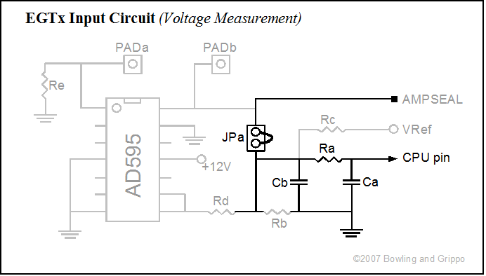
There are component selection tips for the bias resistor, etc., on the general purpose inputs page here. The components on the EGTx circuits have the same designations as the GPIx circuits, so you can use those instruction directly for converting the EGTx circuits.