MegaShift™ 4L80E Wiring
MegaShift™ 4L80E Wiring
This page provides information on how the 4L80E automatic transmission from General Motors operates with the MegaShift™ controller, as well as the TunerStudioMS settings needed to configure the controller.
The 4L80E is a 4-speed (with overdrive), electronically controlled transmission, with ratios:
| Gear | Ratio |
| 1 | 2.482 |
| 2 | 1.482 |
| 3 | 1.000 |
| 4 (OD) | 0.750 |
| Reverse | 2.077 |
There are 40 teeth for the VSS sensor, and 31 teeth for the input shaft speed sensor.
Build information for the GPIO board to use MShift™ with a 4L80E is here: build guide The 'bill of materials' is here: 4L80E bom
The 4L80E is controlled through 11 pins. These are:
| L | Temperature Sensor Signal |
| M | Temperature Sensor GND |
| N | Pressure Switch A (aka. Pin A) |
| R | Pressure Switch B (aka. Pin B) |
| P | Pressure Switch C (aka. Pin C) |
| n/a | 2WD/4WD Input (ground for 4WD) |
| n/a | Vehicle Speed Sensor (VSS input & output) - has its own 2-pin connector |
| Control | Limits | ||
| A | Sol A (1-2) Switched GND | On/Off | 20-40 Ohms (0.75 Amps Max.) |
| B | Sol B (2-3) Switched GND | On/Off | 20-40 Ohms (0.75 Amps Max.) |
| C | Pressure Control Solenoid High | Power (nominal +12V) | Switched 12V from harness |
| D | Pressure Control Switched GND | PWM (293Hz early, 614Hz late) | 0 to 60% (3.5 - 4.6 Ohms at 20°C, 1.1 Amps Max.) |
| E | +12 Volt Power | High (nominal +12V) | Switched 12V from harness |
| S | Torque Converter Clutch Solenoid Switched GND | On/Off | 20-40 Ohms Early / 10-15 Ohms Late (PWM) (1.5 Amps Max.) |
The main difference between the 4L80E and the default 4L60e output pattern is the pattern for solB (output2) is 'inverted':
| Gear | 4L80E | 4L60E |
| P/N | off | ON |
| R | off | ON |
| 1 | off | ON |
| 2 | off | ON |
| 3 | ON | off |
| 4 | ON | off |
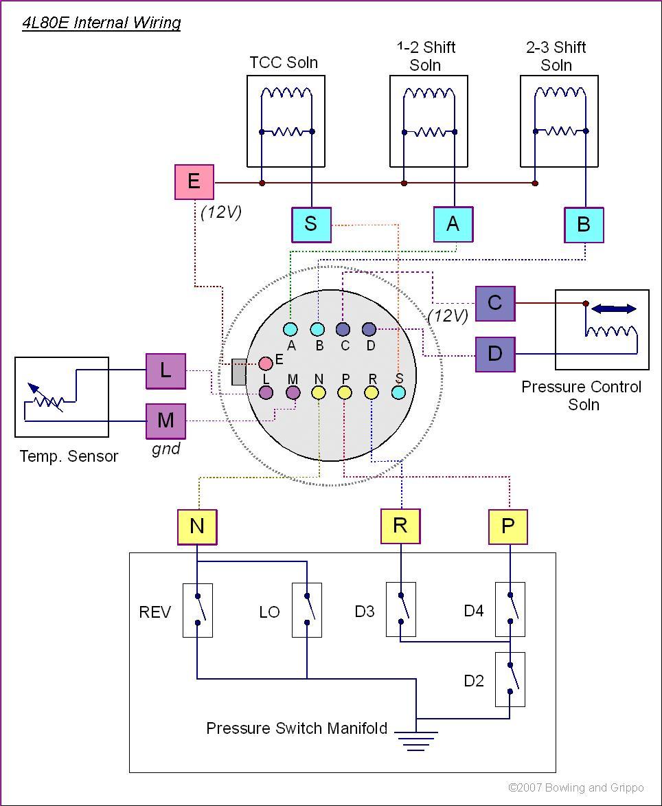
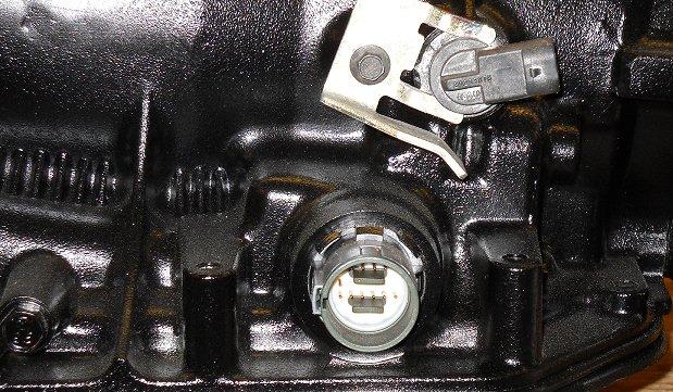
The wiring inside the 4L80E transmission looks like this:
The corresponding AMPseal connections for the control/sense functions are:
Function | Port | Circuit | AMPseal Pin |
| Sol A | PE4 | VB3 | 23 |
| Sol B | PM2 | VB4 | 35 |
| PC | PT2 | PWM3 | 33 |
| TCC | PT3 | PWM2 | 32 |
| switchA | AD0 | EGT4 (jumper) | 26 |
| switchB | AD1 | GPI2 | 6 |
| switchC | AD3 | EGT3 | 25 |
| Input VSS | PT5 | VR3 | 14 |
| Output VSS | PT0 | VR1 | 2 |
| Temp Sensor | AD2 | GPI3 | 30 |
| Brake Sense | AD7 | GPI4 | 3 |
| Speedo Output | PT4 | PWM1 | 31 |
| non-CAN MAP/TPS/MAF | AD5 | EGT1 | 24 |
| line pressure sensor | AD4 | EGT2 | 27 |
| 2WD/4WD switch | PE1 | GPI1 | 5 |
| Spare Output1 (Clutch) | PT7 | VB1 (jumper) | 11 |
| Spare Output2 (Clutch) | PA0 | VB2 | 12 |
| Paddle UP | PT6 | VR2 | 15 |
| Paddle DOWN | AD6 | GPI5 | 4 |
| LED1 | PM4 | GPO1 | 10 |
| LED2 | PM3 | GPO2 | 7 |
| LED3 | PM5 | GPO3 | 8 |
| LED4 | PB4 | GPO4 | 9 |
In addition there are:
| Power In (+12V) | 1 |
| Power Grounds | 18, 19, 20 |
| Vref (+5V) | 28 |
| Sensor Ground | 17, Temperature/VSS/pressure sensor ground |
| CANH | 13 |
| CANL | 16 |
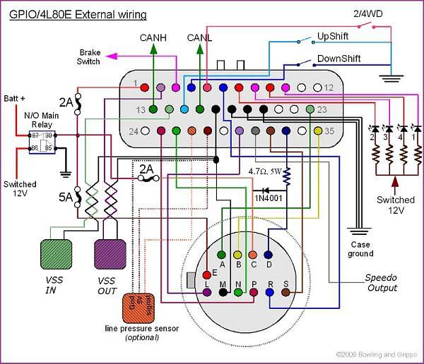
On the GPIO, the connections are:
On MS-II™, MS-III controllers, the CAN paths are:
The CAN termination resistors are already in place on the MS-II™ and GPIO.
To wire the 4L80E transmission to the GPIO board, you need to make a number of connections:
You need a minimum 4.7 Ohm (or higher resistance - up to ~10 Ohms), 10 Watt (or more) resistor (such as Digi-Key 4.7CWBK-ND, $1.67) on the pressure control solenoid wire from the trans connector pin D to the GPIO board's pin 33. This resistor dissipates up to 4 Watts of power at low line pressures (maximum PWM percentages). As a result, the resistor can get hot, so mount it on a heat sink (ideally a metal block) in an area with plenty of air circulation. In conjunction with that resistor, you will need a 1N4001 diode placed between pin C and D on the 4L60E connector (the closer to the transmission connector the better). These two additional components cut the flyback spikes from the solenoid to manageable levels preventing damage to various GPIO board components and potentially cleaning up external signals such as the VSS.
If you want a 'mode selection switch' to force auto mode or enable manual mode, you can do this with a switch and two diodes (1N4001 or equivalent):
(This circuit only works with 'Shift Button Polarity' = "active low".)
When the mode switch is closed, auto mode will be used, regardless of what you do with the shift buttons. If the mode switch is open, pushing either the upshift button or downshift button will put you in manual mode (and pushing both OR switching the mode select switch to auto will put you back in auto mode).
The four resistors for the LEDs can be 330 to 390 Ohms, 1/4 Watt.
If you are looking for a 4L80E harness connector, try a scrap yard, or here: www.currentperformance.com/Connectors/LS1_LS6.html
Sensors:
The 4L80E uses three types of sensors:
| Shift Pattern | Sol A (1-2) | Sol B (2-3) | TCC Sol (LU) | Pressure Control solenoid Sol | Ratio |
| Park | ON | OFF | N/A | ON * | N/A |
| Reverse | ON | OFF | N/A | ON * | 2.077 |
| Neutral | ON | OFF | N/A | ON * | N/A |
| 1st | ON | OFF | ON/OFF** | ON * | 2.482 |
| 2nd | OFF | OFF | ON/OFF** | ON * | 1.482 |
| 3rd | OFF | ON | ON/OFF** | ON * | 1.000 |
| 4th | ON | ON | ON/OFF** | ON * | 0.750 |
Solenoids:
| Solenoid | Resistance (Ohms) | Typical Inductance (milliHenries) |
| Solenoid A | 20 - 40 | 43.0 |
| Solenoid B | 20 - 40 | 43.0 |
| TCC | 20 - 40 E / 10-15 L | 56.9 / - |
| Pressure Control | 3.5 - 4.5 | 8.1 |
Pressure Switch Manifold
The pressure switch manifold (PSM) is a multiple switch assembly consisting of 5 normally open (NO) pressure switches.
Fluid from various hydraulic control circuits is fed to this the pressure switch manifold which allows the ECU to determine which gear the shift lever is currently shifted into (not necessarily the actual gear the transmission is in). The switch contacts are normally open and close when fluid pressure causes them to. Depending upon the circuit, the switch may provide a ground path when closed. The table below shows a pin that is grounded by the PSM as a "0", while an open circuit shows a 12 (volts).
| Gear | Pin N | Pin R | Pin P |
| Park | HIGH | low | HIGH |
| Neutral | HIGH | low | HIGH |
| Reverse | low | low | HIGH |
| 1st | low | HIGH | HIGH |
| 2nd | HIGH | HIGH | HIGH |
| 3rd (Drive) | HIGH | HIGH | low |
| 4th (Overdrive) | HIGH | low | low |
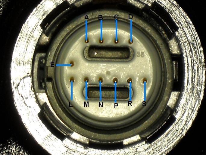
Case Connector
| Pin | Function |
| A | Sol A (1-2) Switched GND |
| B | Sol B (2-3) Switched GND |
| C | Pressure Control Solenoid +12V |
| D | Pressure Control Solenoid Switched GND |
| E | +12 Power |
| L | Temperature Sensor Signal |
| M | Temperature Sensor GND |
| N | Pressure Switch A |
| R | Pressure Switch B |
| P | Pressure Switch C |
| S | TCC Solenoid Switched GND |
Main Line Pressure Tap
MegaShift has a line pressure sensing/logging function built it. It is digikey MSP6907-ND for $114. It's a 0.5-4.5 Volt output (accuracy ±5 psi), and has just a three wire hookup:
It has a 1/8 NPT fitting - the same as the transmission port. However, a 90° elbow, or maybe even some tubing, will be required in most installs to keep the sensor away from the transmission tunnel.
4L80E Temperature Sensor Output
The 4L80E temperature sender can use the default sensor curve built in to the MShift™ code [with the default bias resistor (2.49K Ohms)]:
| °C | °F | R (Ohms) |
| -40 | -40 | 100544 |
| -28 | -21 | 52426 |
| -16 | -10 | 18580 |
| -4 | 23 | 12300 |
| 0 | 32 | 9379 |
| 7 | 40 | 7270 |
| 19 | 68 | 3520 |
| 31 | 86 | 2232 |
| 43 | 110 | 1200 |
| 55 | 131 | 858 |
| 67 | 145 | 675 |
| 79 | 176 | 333 |
| 91 | 194 | 241 |
| 103 | 213 | 154 |
| 115 | 239 | 115 |
| 127 | 260 | 79 |
| 139 | 284 | 60 |
| 151 | 302 | 47 |
Most of the default settings for the 4L60E in the MShift™ code apply to the 4L80E as well. However, there are a few differences:
| Gear | 4L80E | 4L60E |
| P/N | off | ON |
| R | off | ON |
| 1 | off | ON |
| 2 | off | ON |
| 3 | ON | off |
| 4 | ON | off |
You can use the on/off output for TCC control if you prefer, of course, though the TCC engagement might be a bit harsh.
| Gear | 4L80E Ratio |
| 1 | 2.482 |
| 2 | 1.482 |
| 3 | 1.000 |
| 4 (OD) | 0.750 |
| Reverse | 2.077 |
This is how these settings should look in TunerStudioMS:

The settings image above was contributed by Guillaume Scheidt, who is forum user 'gui67'. Please verify it before using. Many thanks to Guillaume for permitting us to display it here.
Here is a draft MSQ (for 2.007 code) for the 4L80E with the changes mentioned above (including the PWM TCC):
The values in this MSQ are for an early 4L80E with a 293 Hz pressure control solenoid and dithering. Check all settings carefully to be sure they are right for your transmission.