General Purpose Input/Output Board Hardware
Search the GPIO manual:
This is the general assembly and troubleshooting guide for the GPIO board from Bowling and Grippo. If you are looking for application related advice/instructions, see:
The general purpose input/output (GPIO) board is an expansion board for MegaSquirt-II™ and related controllers. It provides a number (up to 25) of additional inputs and outputs for MegaSquirt-II. The additional I/O lines are communicated over a CAN (controller area network) which allows communication between the GPIO and MegaSquirt-II™. This allows there to be just two wires connecting the MegaSquirt-II™ and the GPIO, while still sending any number of I/O signals.
The 'features' of GPIO are:
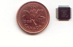
- The GPIO board has the HCS12 C64 processor and CAN (controller area network) chip, which are identical to those on a MegaSquirt-II™ controller (other than a R82, 120 Ohm termination thru-hole resistor), and a separate serial connection (based on the MicroSquirt® controller schematic),
- The GPIO board is designed so that more than one can be used with the controller automotive network (CAN). In fact, up to 15 CAN enabled boards (GPIO or router boards) can be used with your MegaSquirt-II™ controller, giving a very large number of possibilities. All of the boards can be controlled from TunerStudio. A system with two GPIO and one router board might look like this:
TunerStudio/Laptop <--serial--> MS-II™/MegaSquirt® <--CAN--> GPIO <--CAN--> ... <--CAN--> GPIO
where TunerStudio running on a PC is connected to the network over the one serial line, and the main board receives and relays messages over CAN and back to TunerStudio. The first (the MegaSquirt® controller itself) and last board in the CAN chain need to have termination resistors (R82) installed, the other boards should not have R82 installed. See this link for more info on CAN and how to set it up.
- There are 3 types of input circuits and 3 types of output circuits. These are:
- Inputs
- 5 general purpose inputs [GPIx], which can have voltage or resistance input, depending on build-time options (based on the V3 sensor input circuits), these can also be used for software debounced on/off switches,
- 4 VR inputs [VRx] (based on Bruce's EasyVR schematic), for things like transmission controller, vehicle speed indications, or traction control,
- 4 EGT circuits [EGTx] (using AD595 chips), for independent exhaust gas temperature measurements. (These can also be configured for resistance or voltage measurements, similar to the GPIx circuits)
- Outputs
- 4 general purpose outputs [GPOx] (which have user selected 5V or 12V pull-ups, flyback, and LED capabilities),
- 4 PWM outputs [PWMx] (based on the uprated V3 PWM FIdle TIP120 circuit),
- 4 high current circuits [VBx], using the VB921 ignition module driver.
- Any of the I/O circuits can be used for direct port access (such as switch input - debounce in software - or for things like ignition module control (with provisions for a current limiting resistor). There is a 'quick start' to programming using the inputs/outputs here: I/O Quick Start,
- The 35 pin AMPSEAL weatherproof connector is used.
- The serial connection is via a stereo jack (or optionally it can be jumpered to the AMPSEAL connector).
- The GPIO 4-layer (two signal planes sandwiching ground and power planes) board is a mix of surface mount devices (SMD) and regular components to maximize the build time options.
- The GPIO board is 4.00" by 6.00" (101.6mm x 152.4mm) in size, the same as the MegaSquirt® main boards. It is designed to go into the same specification case as a MegaSquirt® PCB (the end-plates are different, of course!).
The serial connector is NOT the primary connection to the system, most communications (everything other than re-flash) will typically be done over CAN to the main board, including configuration and datalogging.
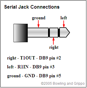
Unlike MegaSquirt® EFI Controller, the GPIO Board does not use a DB9 connector for serial communications. Instead it uses a 2.5 mm (aka. 3/32") sub-miniature stereo jack, of the same spec used for the Innovate LC-1 wide band controller:
This cable is supplied with production GPIO units, but not beta units. If you have a beta GPIO board, or if you have lost your cable, you can build it from Digi-Key parts. To build this cable (if you don't already have one):
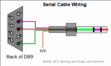
Solder the leads from the 2.5mm stereo plug cable {Digi-Key CP-254CS-ND} to the DB9 connector {Digi-Key 4109FE-ND}. The wires are soldered to the pins as follows:
| Wire Color | DB9 Pin |
| Black | 2 |
| Red | 3 |
| Green | 5 |
| Yellow | no connection |
Note the the pins are numbered on the face of the DB9 (they are imprinted in the plastic), and the pins go straight-through to the solder cups. See the illustration below for clarification.
You can make your own serial cable, the illustrations below might help.
This was done because the serial connection is used much less frequently with the GPIO board than with MegaSquirt® EFI Controller, and it allows the serial connection to be sealed.
Optionally, the serial connections can be brought out through the weather sealed Ampseal connector. There are pads labeled Tx and Rx adjacent the serial plug location on the PCB.
The connections are:
- Rx: Jumper from the via marked "Rx" near the bootloader jumper to the via marked "Rx" near the Ampseal connectors rear edge with 20-24 gauge insulated wire. This will bring Rx out on Ampseal pin 21.
- Tx: Jumper from the via marked "Tx" near the bootloader jumper to the via marked "Tx" near the Ampseal connectors rear edge with 20-24 gauge insulated wire. This will bring Tx out on Ampseal pin 22.
- Ground: Use Ampseal pin 17 as a ground.
©2006, 2012 Al Grippo and Bruce Bowling and Lance Gardiner - All rights reserved. MegaSquirt® and MicroSquirt® are registered trademarks.