MegaShift™ V6 Settings
MegaShift™ V6 Settings
V6.1xx MegaShift™ code is the latest release code for controlling automatic transmissions using the GPIO board form Bowling and Grippo. This code has:
The LEDs or LCD display can be set to flash in reverse.
| Build Guide | Components | Installation | Set-up | |
| 4L60E | 4L60E Build Guide | 4L60E BOM | 4L60E Install Guide | Configuration and Tuning Guide |
| 4L80E | 4L80E Build Guide | 4L80E BOM | 4L80E Install Guide | Configuration and Tuning Guide |
| 41te | DRAFT 41te | DRAFT 41te BOM | DRAFT 41te Install Guide |
Configuration and Tuning Guide |
Jump to the: Set-Up and Tuning Parameters.
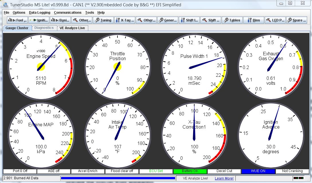
The Windows 9x/ME/XP/Vista software applications you use to tune and configure your MegaShift™ hardware are called TunerStudio by Phil Tobin. You also need a laptop or notebook computer and a conventional serial port (or USB-serial adapter) to communicate with MegaShift™.
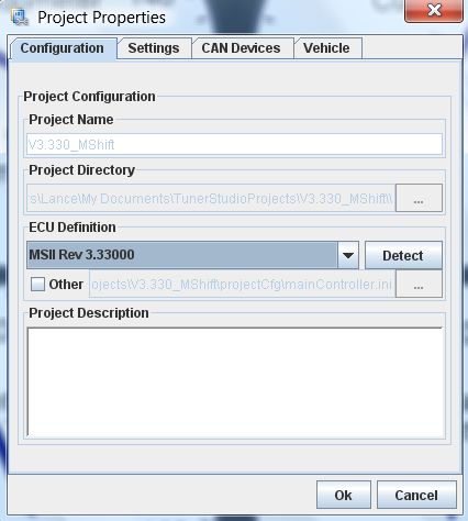
To set up TunerStudio to use MShift™ with CANbus from MS-II™:
| Activated | Deactivated |
|
|
|
Note: The way the code and INI handle metric conversions has changed from older (4.122 and earlier) codes. You MUST set your units before loading an old MSQ. When upgrading from older code, be sure to save the old user parameters in a MSQ, load the new code and set up the new INI, change your units (Project -> Project Properties -> Settings: CELSIUS and SI_LENGTHS) to what you used when creating the older MSQ before finally loading the old MSQ file. The defaults are for both settings to be deactivated (i.e. Imperial units). Otherwise the values will be converted again (i.e. twice, so they will be incorrect) when you change the units settings. Once the units are set, you don't have to worry about this anymore.
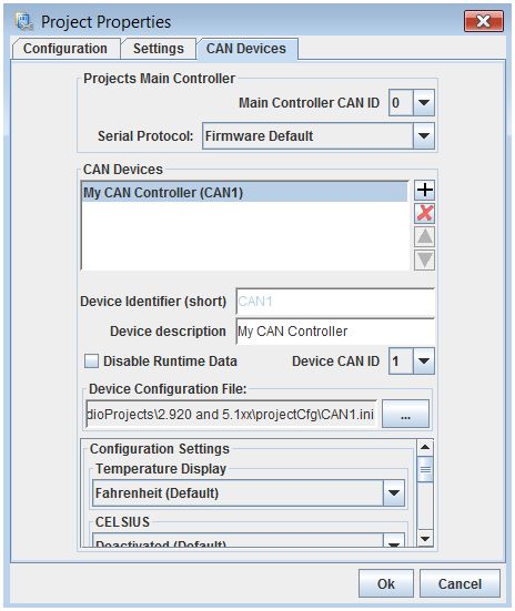
However, to prevent people accidentally screwing up their comms, it is un-editable in the INI file until you make a small change. Use a text editor and find a line in the INI like:
[pre]field = "!MS-II CANbus ID", ms2canID, { 0 } ; change to { 1 } to make editable[/pre]
and change it to:
[pre]field = "!MS-II CANbus ID", ms2canID, { 1} ; change to { 1 } to make editable[/pre]
Here is a video on setting up CANbus in TunerStudioMS: CANbus set-up video (22 MBytes)
There is more on the CANbus pass-through here: www.msgpio.com/manuals/mshift/cpt.html, including assembly and wiring instructions, etc.
The following is a list of of all the tuning parameters in the MShift™ V4.1xx software, and each has a description of how that parameter is used. Pressing F1 at any menu in the tuning software while connected to the internet will take you directly to the corresponding spot in this file.
Note: DO NOT power off the MShift™/GPIO board while the 'Flash Burn' indicator is active. Doing so *will* corrupt your settings. Wait a second or two for the burn to complete before powering down the board.
TunerStudioMS can store and retrieve set-up files, both entire set-ups (.msq files), and gear or line pressure table files (.vex).
You can see the images 2x larger by right-clicking on them, and selecting 'View Image'.
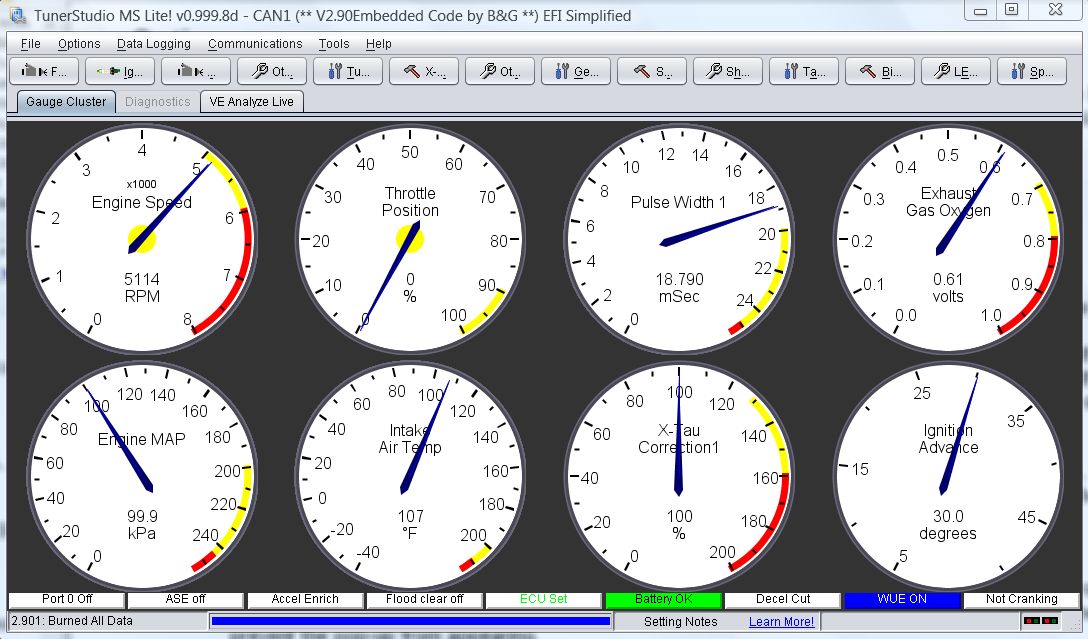
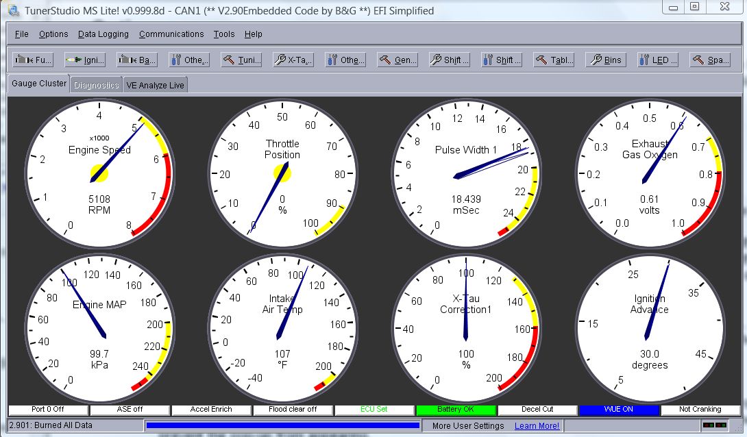
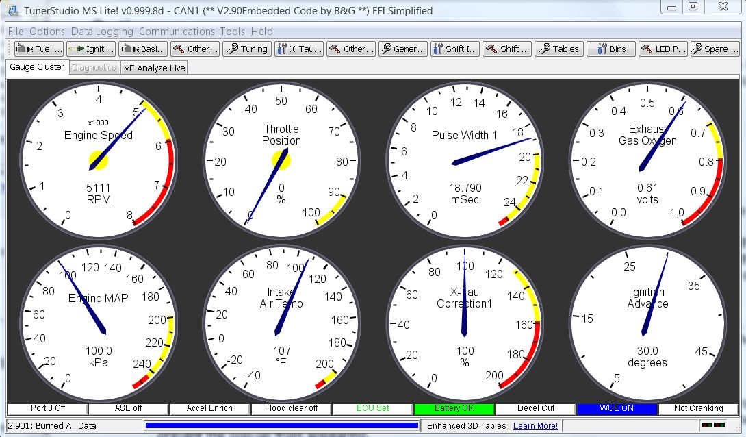
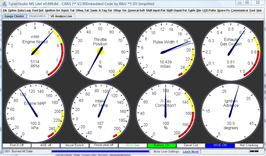
This is without 'MegaTune Style':
This is with 'MegaTune Style':
The datalogged variables are:
| Time | This is the actual time calculated from the PC system time. | |||||||||||||||||||||||||||
| Seconds | Clock, time is seconds since last restart, reset, or 'roll-over' of the clock to zero (from 65535 seconds) | |||||||||||||||||||||||||||
| Mode | Current shift mode: 0=manual, 1=auto (table), 2=auto (sequential) | |||||||||||||||||||||||||||
| Speed | Current vehicle speed (in mph or kph, depending on Metric_Units) | |||||||||||||||||||||||||||
| RPM | Current engine rpm (from MS-II™ CANbus or using ISS/tach input circuit or estimated from VSS and gear) | |||||||||||||||||||||||||||
| miles/kms | Trip odometer - since the controller's last restart/reset (in the units noted). | |||||||||||||||||||||||||||
| load | Engine load reported from your MS-II™ engine controller using CANbus, or determined using local circuit | |||||||||||||||||||||||||||
| WOT | This values indicates if the engine has been to WOT status in the last ten seconds. It is zero if it hasn't, and counts up to ten and resets otherwise. | |||||||||||||||||||||||||||
| mpg | Fuel efficiency in miles per U.S. gallon | |||||||||||||||||||||||||||
| In1adc | Manual gear lever position ADC count for Input1 (processor pin PAD00 on GPIO board circuit EGT4 using Ampseal pin 26) | |||||||||||||||||||||||||||
| In2adc | Manual gear lever position ADC count for Input2 (processor pin PAD01 on GPIO board circuit GPI2 using Ampseal pin 6) | |||||||||||||||||||||||||||
| In3adc | Manual gear lever position ADC count for Input3 (processor pin PAD03 on GPIO board circuit EGT3 using Ampseal pin 25) | |||||||||||||||||||||||||||
| In4 | When 4 input channels are used to determine the shift lever position, this indicates whether that 4th input is high (=1) or low (=0) | |||||||||||||||||||||||||||
| solst | The state of Output1 is logged as the first bit of solst. The state of Output2 is logged as the second bit of solst. The state of Output3 is logged as the third bit of solst. The state of Output4 is logged as the 4th bit of solst, and so on. Zero in any position means off, 1 means on. So some examples are:
00000000 = 0 - Output1 off, Output2 off, Output3 off, Output4 through Output8 off | |||||||||||||||||||||||||||
| upbutton | Indicates whether the upshift button has been pressed. | |||||||||||||||||||||||||||
| downbutton | Indicates whether the downshift button has been pressed. | |||||||||||||||||||||||||||
| fUP | Indicates whether an upshift is being forced by the rpm checking option Normally 0, this value will be 1 if a forced upshift is requested based on the current rpm (if 'rpm checking' is enabled). | |||||||||||||||||||||||||||
| fDWN | Indicates whether a downshift is being forced by the rpm checking option. Normally 0, this value will be 1 if a forced downshift is requested based on the current rpm (if 'rpm checking' is enabled). | |||||||||||||||||||||||||||
| butADC | When a voltage based shifter is used, this gives the current voltage level of the shifter input signal. | |||||||||||||||||||||||||||
| cGear | Current selected gear determined from state of shift solenoids and output tables | |||||||||||||||||||||||||||
| tGear | This is the gear the controller wants the trans to be in. Normally, it is the gear to shift to determined from shift table (limited by the manual gear lever position as appropriate). On an under-rev or over-rev condition (if rpm checking is enabled), the target gear is set to the current gear ± 1. This value is still reported if shifting manually using the shift buttons, but the auto shift gear table value isn't used, of course | |||||||||||||||||||||||||||
| mGear | Manual gear lever position determined from switch manifold (GM style) or switch voltage (Ford style) | |||||||||||||||||||||||||||
| TCC | Torque converter clutch state: 0 = unlocked torque converter clutch, 1 = locked clutch | |||||||||||||||||||||||||||
| Brake | Brake status: 0 = brakes off, 1 = brakes on | |||||||||||||||||||||||||||
| OS | Current output shaft rpm, as determined from the VSS sensor output | |||||||||||||||||||||||||||
| IS | Calculated or measured input shaft rpm | |||||||||||||||||||||||||||
| slip | Difference in rpm between engine rpm and input shaft rpm | |||||||||||||||||||||||||||
| temp | Transmission fluid temperature | |||||||||||||||||||||||||||
| line | Line pressure in pounds per square inch or bars | |||||||||||||||||||||||||||
| auxCH | Axillary data channel (used for load if no CANbus) | |||||||||||||||||||||||||||
| error | error code:
Ex2: error 65 = 1 + 64 = serial comms okay, low voltage. | |||||||||||||||||||||||||||
| PC% | Pressure Control valve duty cycle (% for PWM) | |||||||||||||||||||||||||||
| Sp0% | If spare port 0 is not used for a speedo output, this is the spare port 0 PWM percentage (from 0 to 100%). This value is interpolated from the 16x9 PWM Percent table if Sp0 is ON (OFF value if Sp0 is OFF).
If spare port 0 is used for a speedo output, this is the shift status, where:
| |||||||||||||||||||||||||||
| Sp1% | Spare port 1 PWM percentage (from 0 to 100%). This value is interpolated from the 12x1 PWM Percent table if Sp1 is ON (OFF value if Sp1 is OFF), and then the code picks the closest PWM% based on the number of 0.128 millisecond ticks available at the user specified frequency. So the returned percentage value may not exactly match the value expected from the table, especially if the PWM frequency is high. Click this link for more information. | |||||||||||||||||||||||||||
| Sp2% | Spare port 2 PWM percentage (from 0 to 100%). This value is interpolated from the 12x1 PWM Percent table if Sp2 is ON (OFF value if Sp2 is OFF), and then the code picks the closest PWM% based on the number of 0.128 millisecond ticks available at the user specified frequency. So the returned percentage value may not exactly match the value expected from the table, especially if the PWM frequency is high. Click this link for more information. | |||||||||||||||||||||||||||
| sLoad | Short term LOAD average | |||||||||||||||||||||||||||
| dbug | Spare debugging variable brought out in TunerStudioMS (default is VSS tooth error count) | |||||||||||||||||||||||||||
| burn | Indicates that a burn of users parameters to flash memory is active. | |||||||||||||||||||||||||||
| FWD | state of 2WD or 4WD switch for speedometer adjustment if enabled - 0 = 4WD, 1 = 2WD | |||||||||||||||||||||||||||
| sp0y | If spare port 0 is not used for a speedo output, this is the index value used for the 9 bin table for looking up the PWM percent for spare port 0.
If spare port 0 is used for a speedo output, this is the TPS value received from the MS-II controller over CANbus. | |||||||||||||||||||||||||||
| sp0x | If spare port 0 is not used for a speedo output, this is the index value used for the 16 bin table for looking up the PWM percent for spare port 0.
If spare port 0 is used for a speedo output, this is the raw speedo value before any correction from the speedo correction table. |
More variables are available for datalogging, you can find these in the [OutputChannels] section of the INI.
This parameter lets the controller configure the pull-ups for use with either a GPIO board or a microTCU. When set correctly, it appropriately configures the lever input 5V pull-ups when using the microTCU™ or GPIO using the PPSAD and PERAD registers.
The PPSAD (Pullup Polarity Select for Analog/Digital) and PERAD (Pullup Enable Register Analog/Digital) registers were set in the previous code, but the respective AD pins were not set to be digital inputs, they were left as ADC pins. In order to activate the pull-ups, the appropriate pins had to be switched from ADC to digital (otherwise the pull-up registers have no effect). The code does this by changing the port inputs from ADCs to digital inputs using the ATD0DIEN register when microTCU is set as the hardware AND digital lever inputs is set. Note that changes to the hardware setting (GPIO vrs. microTCU) require a power cycle to take full effect.
In normal operation, this latest code then assigns:
- 1023 to the input 1, 2, or 3's analog-digital count variable when a port pin is 'high' - greater than about 3.25V, and
- 0 when a port pin is 'low' - less than about 1.75V
(but only if 'digital inputs' are selected for the manual lever determination).
These values are reported in TunerStudio as usual. Assigning 'faked' ADC counts simplified the rest of the code, which was built with ADC counts in mind. This is mentioned here because some users might find it odd that such 'perfect' high and low states are achieved.
The idea has been to make set up simpler, but still allow full control over all aspects of the parameters when required (for advanced users or re-purposing circuits when others have been damaged).
The current choices are:
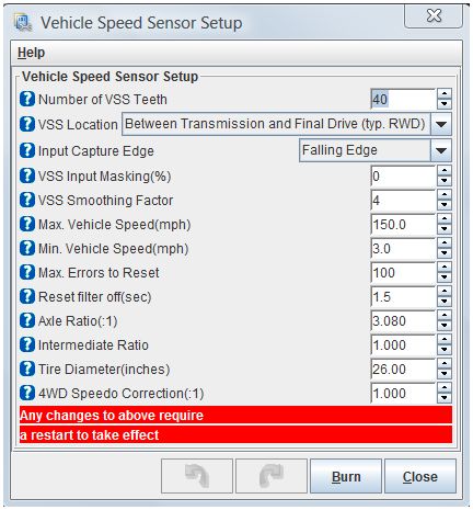
For example, selecting 'General Motors 4L60e' will set the gear ratios (Reverse = 2.290, 1st = 3.060, 2nd = 1.630, 3rd = 1.000, 4th = 0.700), input patterns (swA, swB, swC) and output patterns (SolA, SolB, & 32sol), number of VSS teeth (40). The 4L80e is similar (the gear ratios and output patterns have differences, of course) but also sets the number of ISS teeth (31). There is no practical limit to which parameters could be set using the transmission type setting, but we have to be aware that there may be transmissions families out there that don't all share the same internal gear ratios, for example.
Note that TS may generate a warning when the transmission type is changed because the contents of RAM won't necessarily agree with the local current tune for the affected variables. Once you choose to keep the values on the controller by saving the controller settings as your current tune once or twice this warning should go away.
Finally, note that the settings are only accurate if the controller is wired exactly according to the instructions.
An experimental new parameter called 'Menu Display' has been added (under ''Controller Hardware -> Menu Display'), and has three options: "Show All Menus", "Tuning Menus Only", "Configuration Menus Only". The idea is that some menus (configuration menus) have fixed values and only need to be set initially (internal gear ratios or number of VSS teeth, for example), whereas others ('tuning menus') need to be adjusted to suit circumstances as they arise (shift table, for example).
This parameter can be used to reduce the clutter in the menus. If you uncheck Tuner Studio's 'Show Disabled Menus' under 'Options -> Navigation -> Navigation Options' the inappropriate menus and parameters will not be shown. The parameter setting is only used for TunerStudio, it has no effect in the code at all.
Note: DO NOT power off the MShift™/GPIO board while the 'Flash Burn' indicator is active. Doing so *will* corrupt your settings. Wait a second or two for the burn to complete before powering down the board.
The idea is not to provide another tuning parameter for downshifts, but rather to keep people from over/under-reving their engine (and possibly damaging it) with badly configured shift tables or a mis-timed manual shift.
It is highly recommended that rpm checking be enabled at all times on your vehicle, otherwise an intermittent VSS signal or load signal could potentially cause unexpected and damaging downshifts. The rpm checking can be disabled for use on a trans stim (where the engine speed won't necessarily follow the gear changes).
You must enter the gear ratios built into the transmission.
Enabling burn-out mode effectively makes the trans manually shifted with the lever in the 1st (since the highest gear will be 1st) and 2nd positions (burn-out mode), and then the trans will be automatically shifted according to the shift table if the lever is in 3rd or 4th (or higher if your trans has more gears).
Note that in burnout mode the MShift™ code's rev limiter settings will be ignored.
There is a separate 'shift completion delay' that specifies the period time the controller waits after changing the shift solenoid states for the shift to complete. The shift completion delay is set in a is a function of load, and is an 8-element table that can set under 'Tuning → Shift Completion Delay'. Both the shift completion delay time (in milliseconds) and the load values can be set there, and the value used will be interpolated.
No further shift computations are made during these delay periods.
The hysteresis conditions are for auto mode only, of course. The hysteresis conditions are OR'd. That is, if either condition is met the shift is allowed. However, the hysteresis condition are not used if the load is at WOT.
You can disable the hysteresis by setting the values to zero, or setting the 'Hysteresis Enable Speed' very high (will require mods to the INI, which limits the value to 15),
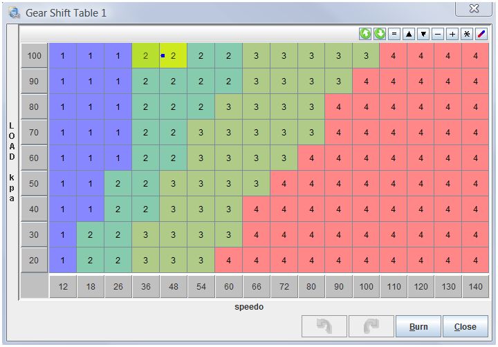
The hysteresis is in there for a reason though. If you have no hysteresis, and happen to be traveling at a nearly constant speed very near one of the shift speeds, the controller could cause the transmission to shift between gears continuously, which would be very annoying. It would be like the TCC switching on and off, but 100 times worse.
And if a given speed column has more than one gear in it (most will - because you will want to upshift earlier at low loads - have a look at the default table) then the speed may stay the same but the load change slightly at the shift point (where the gear changes in the table) and cause a shift. This gear change can itself cause a change in kPa (because the rpm changes) and this might result in a shift back to the original gear, and so on. However note that you can do a lot with the 'LOAD Smoothing Factor' to lower the amount of 'bounce' in the load signal.
Note that in a real vehicle (as opposed to testing on a bench), hysteresis won't delay a shift, as long as the gap between speed bins is larger than the 'Shift Factors/Shift Speed Hysteresis' setting and the gap between load bins is larger than the 'Shift Factors/Shift kPa Hysteresis'.
The user can set the shift pressure for each upshift and downshift for output 3 separately from the on/off pressure. If the value is set to zero, Output3 acts like the other solenoids. However, if the value for a particular shift is non-zero (under 'General Settings/Shift Line Pressure Settings'), the pressure during the shift is set to the non-zero percentage. The different pressure starts before the pressure delay, and lasts until after the shift completion delay. This may be useful for 4L60E users who wish to use a reduce line pressure on solC during the 3-2 shift. Note that PWM must be enabled on Output3 (under 'General Settings/Solenoid PWM Setup') to use this function.
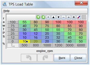
This table is used to look up the adjusted TPS percent based on the raw TPS percentage and the current RPM. The current actual TPS is used as the vertical index, and the current RPM is used as the horizontal index. The interpolated cell value at the intersection of these two value is used as the adjusted TPS percentage (aTPS%).
For example, in the table below, with a raw TPS% of 50% and an RPM of 3000, the adjusted TPS percent used for load calculations would be 70%. If the 'MAP versus TPS for LOAD' parameter was set to 25%, and the MAP was 40 kPa, then the current load would be:
load = 75% × (aTPS%) + 25% × (MAP)
load = 75% × (70%) + 25% × (40 kPa)
load = 52.5 + 10
load = 62.5
When setting the 'MAP versus TPS for LOAD' value, keep in mind that when the engine speed (rpm) drops after an upshift, but the throttle opening remains the same, the MAP (in kPa) will rise (approximately in proportion to the decrease in rpm). The converse happens on downshifts. This is despite no significant change in the throttle position or vehicle speed (so no change in "driver demand"). This change in load moves the load index to a new part of the shift table. The change in the index for the shift table can result in oscillating shifts. So the best advice is to use TPS (the one factor that is least likely to change much during a shift) as much as possible for load (i.e. set 'MAP versus TPS for LOAD' to a low value by moving the slider to the left).
The TPSxRPM table can be setup under 'Tables → Load table TPS by RPM'.
In general, you want to set the table cell values to to provide the most constant TPS that still reflects the driver's demand for torque. You can do this by restricting the range as various RPM's. For example, in the table below the lowest RPM adjusted TPS percentage (aTPS%) can only go from 10% to 55%, while the highest RPM aTPS% can only range from 50 to 100%.
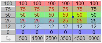
The TPS Load table can be used in a number of ways, so you may need to experiment with different approaches to find what works best for your application.
If user really wants to use only the raw TPS for load with no adjustments, they can set the table so the the cells in each TPS row are identical to the bin value for that row, then the output from the table will be the raw TPS, like this:
Decel mode works in 2 ways:
For the decel mode to be triggered:
- the speed must be decreasing (sampled every 1/10th of a second), and
- there is a user TPS threshold setting which the current TPS value must be below (default is 12%), and
- the Max. sLoad setting (below) must not be zero. A zero value disables decel mode completely.
Downshifts based on the table target gear (even from the new lower row) are prevented until decel mode is canceled or expires (or the rpm drops below the minimum), but upshifts from the shift table are allowed. The decel mode will last as long as the speed continues to decrease OR until the 'downshift delay' period expires (the default is 2.5 seconds, this is user-settable).
Downshifts will still occur if the engine rpm falls below the minimum set in the RPM checking menu (if and only if rpm checking is enabled).
Note that fully variable PWM is enabled only on the PC (pressure control) valve in the default 4L60E configuration. This valve has a 1N4001 recirculation diode installed externally between the solenoid power supply and the line to the GPIO board to recirculate the flyback current generated by the PWM. The illustrated instructions are here: Recirculation Diode Instructions. If you enable PWM on Output1, Output2, Output3, Output4, and/or TCC you MUST install an external 1N4001 recirculation diode between that solenoid's voltage supply and the line going to the GPIO board. The banded end of the diode goes to the voltage supply wire, the non-banded end of the diode goes to the line to the GPIO board. Install the diode as close to the solenoid as is convenient. The 1N4001 diode is installed externally to avoid bringing high-voltage noise into the controller. 1N4001 diodes are available at virtually any electronics supply shop. Without this external diode in the PWM circuits, you may damage some internal components.
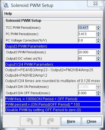
Here is a calculator to help set the ON and OFF parameters based on the target frequency and duty cycle:
You can select which of the outputs (1,2,4,5,6) have PWM, and which are on/off in this menu as well. Note that Output3 is controlled independently.
Also see: PWM Refresh and Dithering
To use any of these (other than 'no slip adjustments'), you must have an independent input shaft speed (ISS) sensor, and the 'TCC/Trans Slip Reporting' must be set to 'Slip in Transmission (ISS/VSS)' under 'ISS/non-CAN Tach Settings'.
The difference is in the scaling of the speedo. This is also used to estimate engine rpm IF the CANbus is not enabled AND PT5/VR3 is not used as a tach input, and/or to estimate the input shaft speed (IF PT5/VR3 is not used for ISS input).
The masking is set as the average of the last 20 periods plus or minus the user input percentage.
The lower limit is the average period minus (input_mask/2); the upper limit is the average period minus input_mask.
For example, if you enter 33%, and the current count for the 20 periods is 1440 (= 1440/20 = 72 tics/tooth), then the mask is set to accept periods from 72-(33%/2) = 72-(0.165*72) = 60 tics to 72+33% = 96 tics. So the range is not based on 100% being no filtering. Instead, low numbers mean more filtering, high numbers mean less filtering (the INI limits the range to a maximum of 200% - higher numbers will break the code).
As of 2.122 code, you can disable the VSS input signal masking by setting this value to zero (0). This may help with speedometer gauges that become jittery, spastic or stuck. If you do not set this value to zero, set it to at least 50. Values lower than 50 may cause the speedometer to respond very slowly.
The default VSSsmoothFactor is 4, so if the current speed is 20 and the VSS indicates it has risen instantaneously to 25 (usually because of noise), the calculation is:
The controller recalculates this 100 times per second, so the 'real' speed can still rise or fall quite rapidly. The smoothing factor can be from 2 to 12 (limited in the INI file).
VSS smoothing is disabled if the current vehicle speed is less than 1.5 times the 'Min. Vehicle Speed' (below) to prevent the speedometer from being stuck at zero if the minimum speed is high.
These fuel efficiency factors allow MegaShift™ to compute the instantaneous fuel consumption.
Timing retard values are positive to remove timing from the MS-II™ engine controller spark advance table. Retard values are applied for the duration of the shift, which includes the 'shift pressure adjustment delay' and the 'shift completion delay' times (under 'General Settings/Shift Factors'), plus the very short time required to process the shift solenoid switching.
So, for example, if you shift from 1st to 2nd, and the upshift retard is 10°, and the second gear retard is 2°, with a base timing of 20° you would see on the timing gauge:
These timing adjustments have been extensively tested with MS-II™ and B&G code, where they work perfectly. Apparently these timing adjustments do not work in MS3 as of Nov.23, 2011, presumably due to a bug in the CANbus code for MS3. Contact the MS3 developers on their forum at www.msextra.com to see if this bug has been fixed at the time you read this.
This sensor has a 1/8" NPT fitting. However, a 90° elbow, or maybe even some tubing, will be required in most installs to keep the sensor away from the transmission tunnel. Note that other internal values can be burnt to the controller to accommodate other sensors, but it might be easier to convert the ADC count in the tuning software.
For example: Suppose 0bar = 0.5v and 20bar = 4.5 volt.
There are 1024 ADC count to cover 0.0 to 5.0 Volts. So:
0.5V = 0.5/5.0*1024 = 102 ADC counts, and
4.5V = 4.5/5.0*1024 = 922 ADC counts.
So the pairs we have are:
(102 counts, 0 Bar) and (922 counts, 20 Bar).
The slope is then:
m = rise/run = (20 - 0)/(922-102) = 20/820 = 0.0244 Bar/count
The y-intercept is:
b = y - mx = 20 - 0.0244*922 = 20 - 22.488 = -2.488 Bar
(this is the theoretical pressure when the Voltage is zero (if everything was linear).
This sets up a pressure sensor based on two (voltage, pressure) points. All the slope/intercept calculation is done internally, so the user doesn't have to do the math. There are four parameters, corresponding to two points:
The further apart the two points are, the more accurate the reported pressure will be.
You can use the 2 point setting to report the Analog-Digital Conversion (ADC) count on the line pressure input by changing the settings to:
You can read more about ADC counts here: www.msgpio.com/manuals/mshift/adccalc.html
Also, there is no dedicated gauge for the ADC output, you would have to create one. It would look something like this (add it to the [Gauges] section of the INI):
line_ADC = linepressure, "Pressure ADC", "", 0, 1023, 1, 5, 1020, 1024, 0, 0
Some PWM solenoids uses a deliberately low PWM percent, but refresh the solenoid with a burst at 100% before it can close. As well, some pressure control solenoids use a cleaning pulse (called a 'dither') to ensure adequate fluid flow through the system to keep the system clean. You can set both of these up in this dialog.
As of 2.122 code (including all 5.xxx code), you can disable the ISS input signal masking by setting this value to zero (0). This may help with input shaft speed/tach gauges that become jittery, spastic or stuck. If you don't set this value to zero, set it to at least 50. Lower values between 1 and 49 may cause the ISS tach to respond very slowly.
Engine speed = 0.750 × ISS
So you would enter 0.750 for 4th, and leave the other values at 1.000.
The user values let you adjust the calculated RPM to account for this for all the forward gears you are lucky enough to have (once you have enabled the ISS above).
Load = ('Multiplier' * deviceVolts) + 'Load at 0 Volts'
Where M = multiplier (aka. "slope" in math terms), x is the Volts, B = Load at zero Volts, and y = load.
M is the slope, which is the 'rise' divided by the 'run':
M = (Load2 - Load1)/(Volts2 - Volts1)
and B = Load1 - M * Volts1
For example, if your device puts out 1.2 Volts at 20% load, and 4.4 Volts at 100% load, then the values you would use are:
Multiplier = (100-20)/(4.4-1.2) = 80/3.2 = 25
Load at 0 Volts = B = y - Mx = Load1 - 25*Volts1 = 20 - (25*1.2) = -10
The equation then becomes Load = (25 * Volts) - 10
Here is a calculator to assist in deriving the values (click anywhere outside a text box to recalculate):