Thanks
Transtim PCB
Transtim PCB
So got my digikey order today so I could build my stim board and it appears that the EG1953-ND rotary switch isnt the right one for the board. Anyone have a recommendation on which one I need to order?
Thanks
Thanks
-
Bernard Fife
- Posts: 1696
- Joined: Fri Apr 04, 2008 1:28 pm
Re: Transtim PCB
zRye,
Does it look like this one?
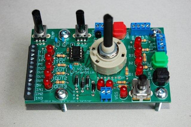
If so, it is probably the correct switch (I have used this switch several times on my trans stim builds).
Note that the instruction manual ( http://www.msgpio.com/manuals/mshift/v2 ... build.html ) says:
Lance.
Does it look like this one?
If so, it is probably the correct switch (I have used this switch several times on my trans stim builds).
Note that the instruction manual ( http://www.msgpio.com/manuals/mshift/v2 ... build.html ) says:
However, it is possible that your supplier (DIYautotune?) has changed the design of the stim, in which case you should check with them for the specification of the correct switch and other hardware.22. Install and solder the 6-position rotary switch (EG1953-ND). If you look at the underside of the switch, you will see the pins are numbered. Put pin #2 towards the large '2' in text meant to indicate 2nd gear. You may have to bend the pins slightly to fit the holes. The pins are a tight fit in the holes, you will have to use a fair bit of force to seat the switch before soldering.
Lance.
"Never wrestle with pigs. You both get dirty and the pig likes it." - George Bernard Shaw
Re: Transtim PCB
Upon further inspection it was that all the tabs on the bottom were slightly off and with a bit of bending them I got it to press onto the board and soldered up 
Re: Transtim PCB
Now im building the GPIO board to control a 4l60E and ran into another question.... should I make a new topic?
Question is, in step E of the build instructions it state if using a GM shifter... probably gonna make my own shifter setup for the project truck it will have Park, Reverse, Drive then a PLUS / MINUS 'Manual' mode. As I havent built the shifter I do not quite know what the requirements of the GPIO setup needs to be for such...
Your thoughts?
"E. GPI1, GPI2, GPI5 (2/4WD, swB (aka. Input2), downshift):
These circuits are arranged in a left-right line just above the center of the board. They are digital input circuits, and ground to activate (no pull-up).
Note, if you are not using a GM style shift lever input (3 digital inputs on swA, swB and swC) you can use swB and swC for datalogging analog voltage signals such as temperature or EGT. To do that, you need to build the circuits differently. See www.msgpio.com/manuals/gpi.htm for more details on different ways to build the GPI2 circuit. You can also use the 2/4WD input for logging digital inputs (if you don't have a 4WD), if you build the circuit appropriately and select the appropriate option in MegaTune.
Install and solder a 1.0K Ohm, 1/8 Watt processor pin resistors {brown-black-red, 1.0KEBK-ND} in R27, R29, and R35.
Install and solder 330 Ohm, 1/8 Watt resistors in R21 and R25. These are the pull-up resistors for the downshift button circuit on GPI5 and the 2WD/4WD switch on GPI1.
Install and solder 5.6 Volt Zener Diodes in:
R28 - banded end goes towards Ampseal connector,
R30 - banded end goes away from Ampseal connector,
R36 - banded end goes towards Ampseal connector.
If (and only if) you are using the digital inputs for the manual gear lever determination such as with a 4L60E (as opposed to a variable voltage, Ford-style potentiometer) then you must add pull-up voltage to GPI2 (and EGT3 and EGT4 in later steps). Do this by installing a 330 Ohm resistor in R22.
Install and solder 0.1µF capacitors {399-4329-ND} in C14 and C22.
Install and solder a 0.001µF capacitor {399-4144-ND} in C16."
-
Bernard Fife
- Posts: 1696
- Joined: Fri Apr 04, 2008 1:28 pm
Re: Transtim PCB
zeroRYE,
As long as the shifter uses 3 digital inputs to signal the shift lever position, use the GM build.
If you need more than 3 digital inputs, or if your shifter will put out a varying voltage signal to indicate the shift lever position (http://www.msgpio.com/manuals/mshift/voltlever.html), then you may need to build the GPIO board differently.
"Never wrestle with pigs. You both get dirty and the pig likes it." - George Bernard Shaw
Re: Transtim PCB
May be a dumb question, as I dont know 4L60E or electronic trans control well and I dont have the trans in front of me yet.
Was planning to adapt an oldschool hurst shifter I have to do the movement, there are def no wires or position sensors on it, can I assume these sensors generally on/in the trans itself? If so it will likely be whatever Gm uses as im not doing anything special to the trans.
Thanks again
Was planning to adapt an oldschool hurst shifter I have to do the movement, there are def no wires or position sensors on it, can I assume these sensors generally on/in the trans itself? If so it will likely be whatever Gm uses as im not doing anything special to the trans.
Thanks again
-
Bernard Fife
- Posts: 1696
- Joined: Fri Apr 04, 2008 1:28 pm
Re: Transtim PCB
zeroRYE,can I assume these sensors generally on/in the trans itself?
Yes, the sensors are in the trans itself, in something called the pressure switch manifold (PSM). You connect the GPIO board to the main connector on the 4L60e, and the shifter position is fed out on pins N, R, and P (aka. switch A, B, and C).
There's more on this here: http://www.msgpio.com/manuals/mshift/wiring.html
"Never wrestle with pigs. You both get dirty and the pig likes it." - George Bernard Shaw