Help configuring DRAC VSS input

A forum for discussing applications and implementations of the MegaShift transmission controller code for the GPIO from B&G. This can control up to 8-speeds and 6 shift solenoids (plus a 16x9 table for controlling a PWM line pressure valve). It has manual and fully automatic modes (16x9 load x speed table), with under and over rev-limit protection, and full data logging of all inputs and outputs (among many other abilities). A TransStim to test your completed board is also available.
Post Reply
flak monkey
Posts: 50
Joined: Sun Sep 21, 2014 11:28 am

Help configuring DRAC VSS input

Post by flak monkey »

Hi guys,

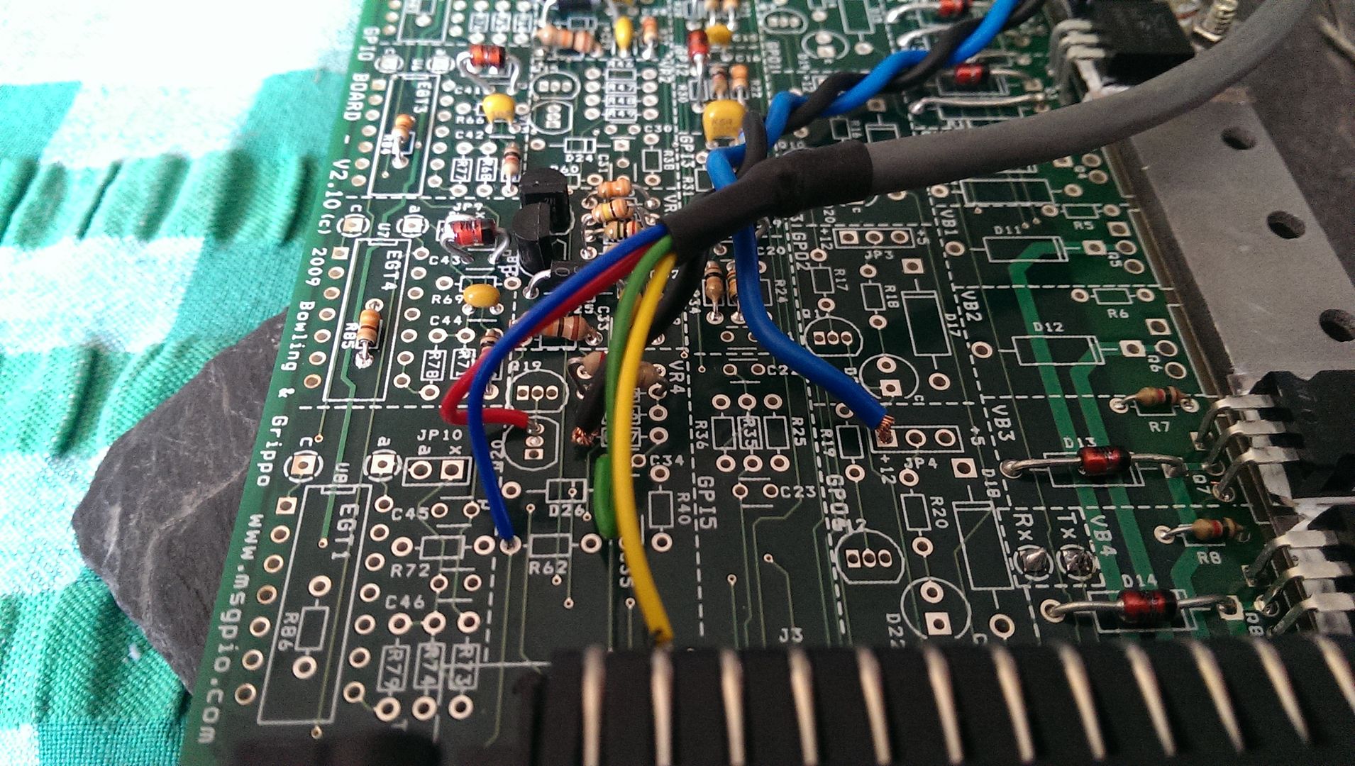
I'd like a little help in using a DRAC to get a better VSS input into my megashift. It's being used on a 4L80E and it's currently build exactly per the build guide here: http://www.msgpio.com/manuals/mshift/4L80E/4L80.html

I have a DRAC being shipped to me as I type this, it's the one in the photo attached. I need a little help understanding how to get the output signal from the DRAC to the GPIO processor - I have a very basic electronics knowledge, but don't wan't to break something! :lol:

I understand that the pin's on the module are:
Smaller connector not used.
7 - VSS Input neg
8 - power ground
9 - +12v ignition
10 - Not connected
11 - VSS output 1
12 - VSS Input positive
13 - VSS output 2
14 - Not connected
15 - Speedo signal (not required for Megashift)

In terms of what's needed to work with Megashift:
Does it matter which VSS output is used on pins 11 or 13?

I understand that the output needs a 1.2k pull up resistor from a 5v source?

What circuit should I build inside the GPIO to take the 5v square wave output from the DRAC to the processor?

Thanks in advance, and sorry for the probably simple questions!
Attachments
DRAC Module
DRAC Module
DRAC.JPG (141.04 KiB) Viewed 10256 times
Bernard Fife
Posts: 1696
Joined: Fri Apr 04, 2008 1:28 pm

Re: Help configuring DRAC VSS input

Post by Bernard Fife »

flak monkey,

I am certainly no expert on these DRACs, so I could be wrong. I will collect any info I can find and create a web page for the DRAC w/ MShift shortly. My best semi-informed guesses are:

Does it matter which VSS output is used on pins 11 or 13? I don't think so.

I understand that the output needs a 1.2k pull up resistor from a 5v source? Yes, that is correct. The value of the resistor likely isn't critical (it can probably be anywhere in the range from 1K to 10K)

What circuit should I build inside the GPIO to take the 5v square wave output from the DRAC to the processor? Because you should have a clean 5V square wave signal from the DRAC, you no longer want a 'zero-crossing detector' circuit (which could trigger on noise during the signal's 'low'). Instead you want to capture an edge where the signal is rising (or falling). In practice, that means detecting a voltage higher than zero volts but lower than 5V. So you will want to increase the trigger threshold voltage a bit. The best way to do this is to lower the resistance of the resistor in R45 (for VSS on VR1). The specified value is 300K Ohms, and you can try from 47K to 220K to eliminate the false triggering on a noisy signal (the lower the resistance, the higher the trigger voltage).

There is a fair bit of DRAC info (in the OEM setting) in this document (which you have probably already seen):
DRAC.pdf
(752.41 KiB) Downloaded 564 times
Lance.
"Never wrestle with pigs. You both get dirty and the pig likes it." - George Bernard Shaw
flak monkey
Posts: 50
Joined: Sun Sep 21, 2014 11:28 am

Re: Help configuring DRAC VSS input

Post by flak monkey »

Thanks Lance, I'll have a play around with this as soon as the module arrives and let you know how it goes.

I'm more than happy to contribute information on using the DRAC w/Megashift when I have something that's functional.

SJ
Bernard Fife
Posts: 1696
Joined: Fri Apr 04, 2008 1:28 pm

Re: Help configuring DRAC VSS input

Post by Bernard Fife »

SJ,

I was looking at this more closely, and you probably want to use pin 11 for the speed signal. This output gives a much lower frequency than pin 13 (which has the same frequency as the VSS signal). That reduces the interrupt overhead for the code.

However, this reduced frequency also means that you'll have to experiment with the VSS set up parameters in the code to get the right speed reading in TS.

If you use pin 13 for the speed signal, then the standard VSS setup should work for you once you enter your number of teeth, final drive ratio, tire size, etc.

BTW, I am try to gather all the DRAC info I can find into this document: http://www.msgpio.com/manuals/mshift/drac.html

Lance.
"Never wrestle with pigs. You both get dirty and the pig likes it." - George Bernard Shaw
flak monkey
Posts: 50
Joined: Sun Sep 21, 2014 11:28 am

Re: Help configuring DRAC VSS input

Post by flak monkey »

The DRAC arrived in the mail today, will get it fitted tomorrow and let you know how it goes :D

Planning on fitting it inside the case and making it a built in module, it looks very simple to remove it from it's case and fit it on the inside of the lid of the MShift. I have an Autometer programmable speedo, drive a mile and push the button sort of deal, so the calibration is really unimportant to me to be honest. I'll use pin 11 as the output due to it's lower PPM :)
flak monkey
Posts: 50
Joined: Sun Sep 21, 2014 11:28 am

Re: Help configuring DRAC VSS input

Post by flak monkey »

Stripped the DRAC out of the case and removed the connector, its a neat board inside the case. I used some multi-core shielded cable to get power and signals to and from the board.

From left to right in the photo below:
Blue - pin 12 - VSS input +ve
Red and yellow - pin 11 - speed pulse output 5v square wave - 2000 pulses per mile
Large blue - pin 9 - +12v supply
Black - pin 8 - ground
Green - pin 7 - VSS input negative

The reason I ran 2 cables to pin 11 is that the output needs a 5v pull up. And instead of putting the pull up resistor on the DRAC board I fitted it on the main GPIO board and then ran a wire back to the DRAC. Sure there's many other ways to do this, but I had enough cores in my cable to do this.

Image

At the other end I considered lots of different options.

Yellow cable - output from the DRAC is connected back to pin 2 of the AMP connector. This takes the signal back to the original output speed sensor circuit on VR1. I changed R45 for a 100k.
Small blue cable - VSS input to the DRAC comes in on the bottom of R62 which is connected back to pin 29 of the AMP seal.
Red cable - 5v pull up comes from the left pin of Q20, via a 1.2k resistor fitted in R55.
Black cable - DRAC ground is connected to the bottom of R57
Large blue - +12v from the bottom of JP4.
Green - VSS negative input - to bottom of C34, ground.

I checked the current draw of the DRAC before connecting it up and it was just over 20mA. Might be more when in use?

See any problems?
Image
Bernard Fife
Posts: 1696
Joined: Fri Apr 04, 2008 1:28 pm

Re: Help configuring DRAC VSS input

Post by Bernard Fife »

flak monkey,

Very nice! Your connections look right to me at a quick glance. I don't imagine the DRAC will draw a lot of current. I would be surprised to see more than about 50 mA or so (a megasquirt main board and stim uses about 200-250 mA, but much of that is for powering LEDs).

Lance.
"Never wrestle with pigs. You both get dirty and the pig likes it." - George Bernard Shaw
Post Reply