Page 1 of 2
Lower VSS trigger voltage
Posted: Mon Apr 01, 2013 4:34 am
by gboezio
Hi there, I'm building a LS2 (LY6)/4l80E MS3/Megashift 84 CJ-7, I'm using a Dana 300 Transfer case, it has a 7/8 cable speedo output, so I have ordered a cable encoder adapter but it's voltage is pretty low I can see 4 to 5V to ground from the sensor, the GPIO won't pick it up most of time, I had signal at some point, but it went away and looked almost random, so what I did, I have soldered a 100k resistor in serie to the 330k one, tried it and had signal, than I desoldered the two and replaced it by 470k resistor, it would not work, so I have replaced it with a 390k, still no joy, if I take the 5V Vref and scratch the sensor wire trough a 1k resistor I can see it jumps, sometimes (maybe the software fill up with errors), I have tried to swap wires with the ISS, still nothing, at the end it was totally dead, not responding to anything, I have spinned the VR sensor with a hand drill, it looks very nice on the scope.
I'm a beginner in electronics and I can see different writings on the two 47 pF capacitors, they are from the same bag, on one I can read 47 followed by a 0 I think and on the other I can read 2k something, they may just be from different manufacturers.
Other than this, the solder on the two transistors are close but I see high resistance between the pins
Overall it "feels" like some high frequency noise can make it to the processor sometimes...
Processor is running I can upshift/downshift
I may need some help for this one, thanks for reading
Giovanni Boezio
Re: Lower VSS trigger voltage or mixed components
Posted: Mon Apr 01, 2013 11:50 am
by Bernard Fife
gboezio,
5V signals are no problem for the VSS input, I often use less than this on the bench. However, the signal has to be clean. If this was mine I would check the advice here:
http://www.msgpio.com/manuals/mshift/vss.html. That page qives tips for using the MShift software to filter out noise in the signal, along with other VSS tips.
Also, if you aren't using the latest code, be sure to do that as several improvements have be made to the VSS processing.
I would also recheck the circuit against the build instructions to make you assembled it spec, and then have a very close look at all the components to make sure solder or residual flux isn't shorting any components (make sure you have washed the board with 99% isopropyl alcohol, rinsed with hot water, then let it dry over night).
Lance.
Re: Lower VSS trigger voltage or mixed components
Posted: Mon Apr 01, 2013 12:15 pm
by gboezio
Update, ok I went to the garage and took many samples, I have lost signal to VR1, and I chased the open between pin 2 and the VR1 circuit to discover that I'm soldering like an idiot, it still don't work as intended, but still I have constant results and I call this improvement.
Now spinning the sensor at a rate of 45 HZ give about twice the hz count on TS, but if I keep increasing the drill speed it catches up
I still have the 390k resistor installed, now trying to figure out what to do
Re: Lower VSS trigger voltage or mixed components
Posted: Mon Apr 01, 2013 1:56 pm
by gboezio
I may trigger the logic with the tip of the sinewave at low speed and trigger two or three times, then the volts rise up and cross only once giving the correct hz count
So I think that I better increase R45 some more, I'm trying to get the best signal before starting to filter with the software to avoid problems down the road.
I will burn the latest firmware on the controller, I have gallons of isopropyl 99% alchool from my fiber optic job, I will wash the board more than I ever washed my own underwear, then I will spray some good sealer on it, maybe permanent since it's sitting on a roofless CJ-7 and moisture is the enemy, I plan on sealing the case and the electronic box may be sealed as well, I will cast pressure plug epoxy on the incoming wires(there is 20 spare wires) and shrink a Raychem sleeve over it, Put a big pouch of silica salt on the bottom, maybe silicone coating is for me
Re: Lower VSS trigger voltage or mixed components
Posted: Mon Apr 01, 2013 10:03 pm
by gboezio
Hi Lance,
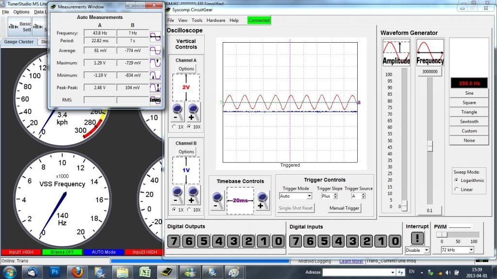
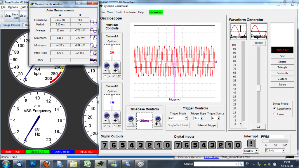
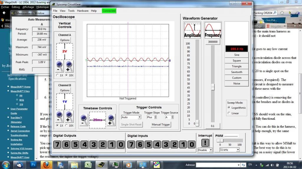
I worked hard on this thing tonight, I swapped resistors, re loaded the code (2,204), and I don't think I have noise at all, but I tried to collect information that can be of any use, I followed the signal path and took measurements at various steps in the chain, the two snapshots of Q14 and Q13 were at peak problem, while reving my sensor with a hand drill at low speed, the sensor start to trigger, the speed could be almost normal but very jumpy, then it maxes out so I held it there to take scope snapshots, I was expecting a lot of triggers (high frequency), but that was not the case the period is correct, but there is incomplete and missing triggers, then I increase the drill speed out of the problem zone the tuner studio speed drops finally to where it makes sense and on the scope the missing triggers show up where they should be, but the frequency increase and I was expecting it to follow the Tuner studio speed (decrease). So low frequency incomplete triggers, trigger a high frequency on the processor like more than 10 times VR1 output.
This is after R37 (probably higher speed than the problem zone)
This was taken after Q14 at peak problem
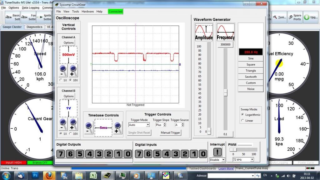
This is the most interesting snapshot taken at peak problem after Q13, speed was maxed out but VSS sensor was spun low

I hope this helps me and you, it may be unclear but if you want I can make a video of how I have measured all this.
Last problem to solve before the build is done !!
Thanks
Re: Lower VSS trigger voltage or mixed components
Posted: Tue Apr 02, 2013 5:56 am
by gboezio
One more question, if I'm trying to use the VR input under it's design limit with this sensor, I have very few other options, but I wonder if two pulses per driveshaft revolutions is too little to get usable speed signal, I could try to read the side of the yoke with a GT101 Hall sensor, that would make a nice 12V square wave.
Edit : will not work casting unequal
Re: Lower VSS trigger voltage
Posted: Tue Apr 02, 2013 8:17 am
by Bernard Fife
gboezio,
Hand drills are horrendously noisy things, and can send noise in through the signal wire, the power supply, or through the air, and cause all sorts of issues. Testing with a signal generator, or in the car with the real wiring and sensors, is generally much more useful.
I can't tell where the ground level is on the scope shots, but it may be that fluctuations near ground are causing added trigger events, in which case you may need to raise the trigger threshold. There are instructions in the link I gave to do this (involving R45). You could also try a weak pull-down in the signal wire (a resistor of about 100K to 1M from the signal wire to ground).
Two pulses per revolution shouldn't be a problem, but try changing it to 20 in the software (so the speed will be 1/10th) and see if that makes any difference (I don't normally check as low as 2teeth/rev, I only go down to 4 or so in my testing normally).
Did you try adjusting the mask and min/max speed values? What effect did that have?
Lance.
Re: Lower VSS trigger voltage
Posted: Tue Apr 02, 2013 8:55 am
by gboezio
Yes I tried to lower the mask setting, still the speed will increase near trigger limit, I have tried 47k 87k (or close), those trigger noise at high speed so too low, 120k (this one works best, but it start very late high speed), 220k 330k 390k, 470k, 1M, I have tried a resistor in serie with the signal, very bad, most of the low speed band in unusable, I have a very solid ground, 3wires 14 ga to the bellhousing soldered on a common #6 lug, I will try the ground pull down.
I could lower the unusable speed limit wile increasing R45, The first stable signal was 135 hz and up
I may try as well to lower the 10kohm inline resistor to raise the usable signal voltage based on the fact that putting another in serie made the worst unusable signal of all except the R45<120k.
Re: Lower VSS trigger voltage
Posted: Tue Apr 02, 2013 8:08 pm
by gboezio
Hi Lance,
I worked a lot on it and there was two different problems, first the trigger will start late while the transmission should be in second gear, and at the trigger edge there was false triggering between the no trigger and the stable trigger.
So I have followed the manual for the R45, I have tried a crazy amount of resistors and sometime 3 to 4 times the same ones, of course I have soldered insulated wires.
The best improvement for early trigger is R37, I was shy on shorting it but I almost did it, it went from 220k to 220 ohms, now I can pickup signal as low as 20hz.
This has to be combined with a pull up resistor on ampseal pin #2, I ended using 330 ohms 220 would make the low side very thin. I have tried to back off toward normal both of these and I was loosing.
On the false trigger side, I could not get rid of all the noise, I could now reproduce by hand the false trigger because now everything is happening at lower speed so that rule out the drill for all the events....but I could trigger the speedo in some configuration with the drill alone !! (R45=1Mohms I think), so I get a stable trigger with R45=47k, I still see noise but as you mentioned my testing setup was less than optimal.
I need your input to know if you think that lowering R37 is a bad thing or if I should change the condenser or do it otherwise for the same result, otherwise I will wash the board and coat it
If that was to do again I would have drilled the transfer case and used a hall sensor on a big gear on the Dana300 transfer case, the tooths were wide and seemed usable.
The only other speed sensor I could think of is my wife, she outputs a high amplitude sinewave and it's frequency is proportional to vehicle speed !!
Next step it to try the Jeep on the road

PS: The Vr sense schematic would help me to fully understand this thing, is there an hysteresis component in this circuit, I could not really figure it out
Thanks for helping me with this issue
Re: Lower VSS trigger voltage
Posted: Wed Apr 03, 2013 7:28 am
by Bernard Fife
gboezio,
If this was mine, I wouldn't coat the board until I was sure I was happy with it. If mine was acting like yours at the moment, I would not be happy with it.
Did you try setting the number of teeth to a number higher than 2? What numbers did you try? Did you try 20 or more? What difference(s) did this make?
Did you try adjusting the minimum and maximum speed values (
http://www.msgpio.com/manuals/mshift/V41tune.html#gv)? What values did you try and what effect(s) did this have?
The VR circuit schematic and other info is here:
http://www.msgpio.com/manuals/vr.htm You can lower R37 down to zero, it is in series with R59 (which is 10K Ohms).
If you could post a close-up picture of the VR circuit, that might help us to see anything that could be out of place. Also, if your scope has two channels, a shot with one channel with the raw signal and the other from the 25x2 header pin (next to the "VR1" label) would be ideal for showing the raw input signal and the result of the VR circuit that gets sent to the processor.
Lance.