Chrysler 41te Trans Control
Re: Chrysler 41te Trans Control Needed By Many!
This will probably turn out to be a dumb question when I look further, but are the range sensor switches JUST pressure sensor switches, or is there some set of electronic switches that sense shifter lever position, and then another set of pressure sensor switches? As usual, I'm confused!
Thad
Re: Chrysler 41te Trans Control Needed By Many!
The one thing I'm still questioning is whether most of these modes actually have the solenoids powered in 100% duty cycle? The reason I'm wondering is that I only see two modes that list a LR/CC solenoid state as "mod". I'm thinking that refers to some sort of PWM going on there to sften the onset of the converter clutch, and maybe where I was assuming that PWM was being used to smooth the transition from one clutch pack to another for a gear change, maybe really it's just straight power to the solenoids, and it's the tiny bleeds in the VB (you've been boring out to get fast shifts, Steve) that are softening the transitions between clutch packs.
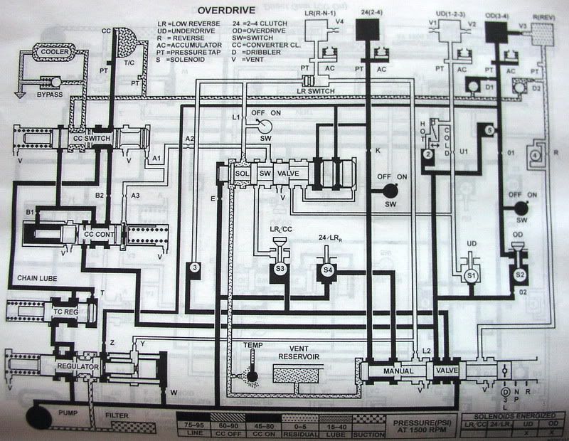
Here are the two modes that list the LR/CC state in the lower right of the page as "mod". The must account for 2nd, 3rd, and OD I think?:
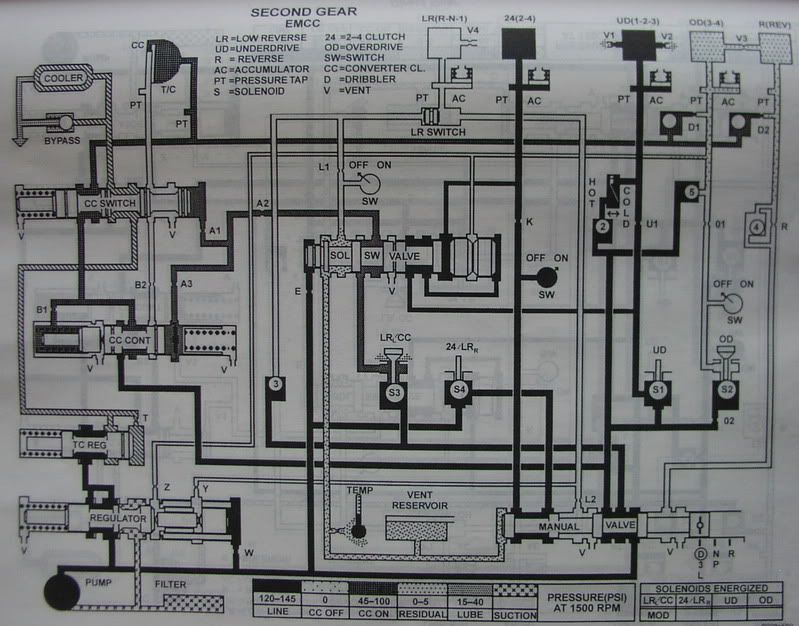
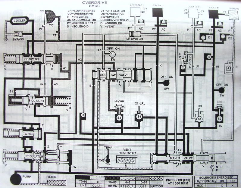
There is no mode shown for 2nd gear with the converter clutch just "on". These are the diagrams for the OD with CC simply "on", and 3rd or "Direct" gear listed as CC "on":
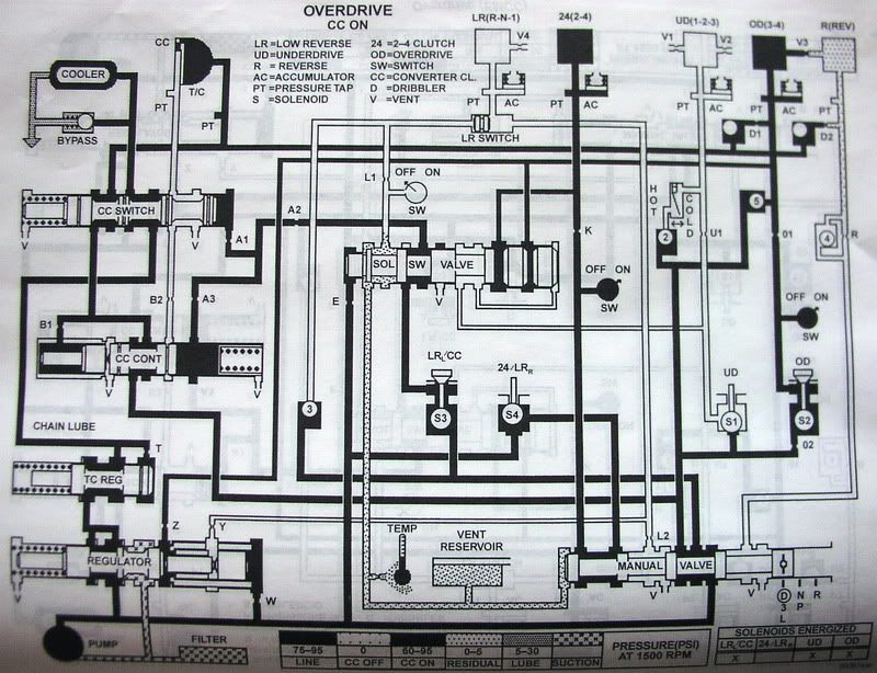
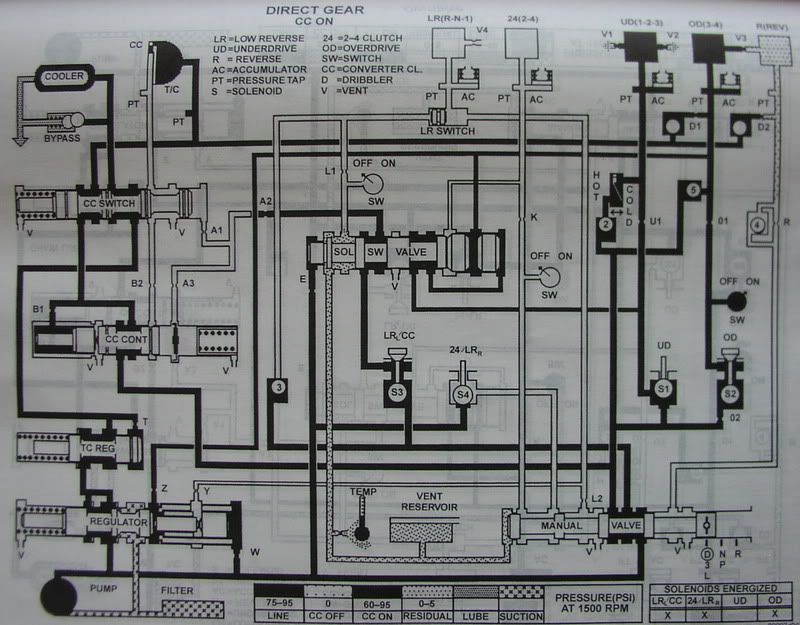
Here are OD, 1st and 3rd without any CC:
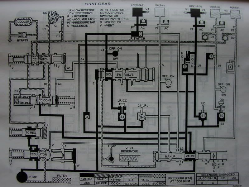
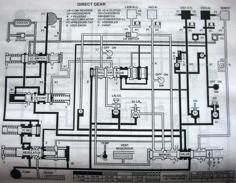
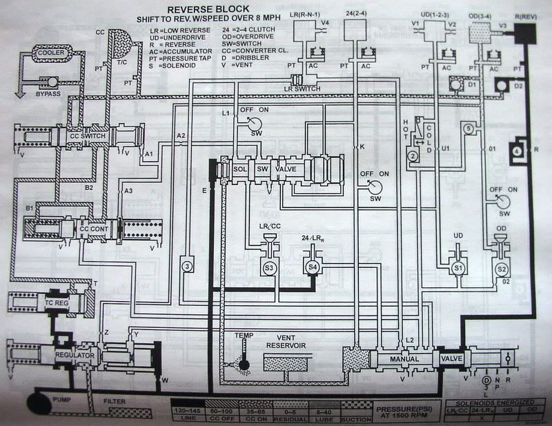
Here are Reverse and 2nd that show no solenoids energized as Steve explained above:
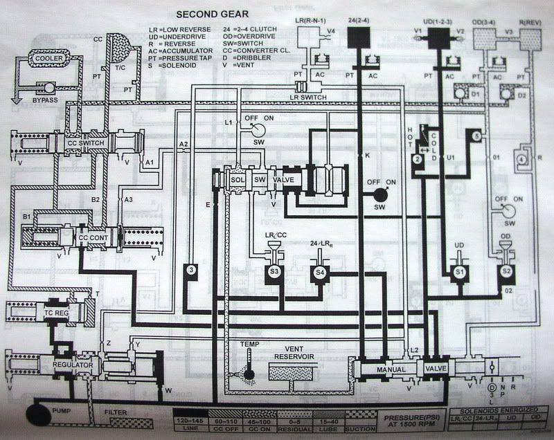
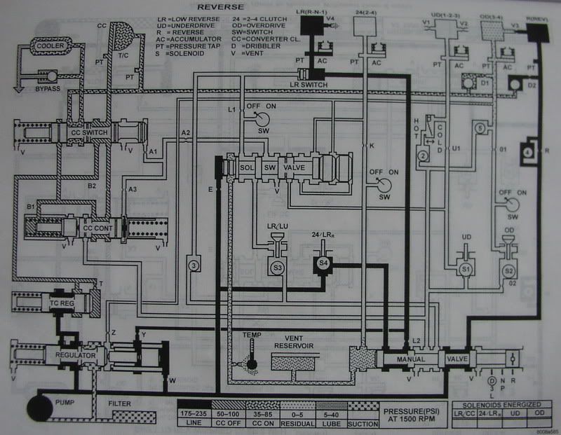
Here's Park/Neutral at less than 8 MPH:
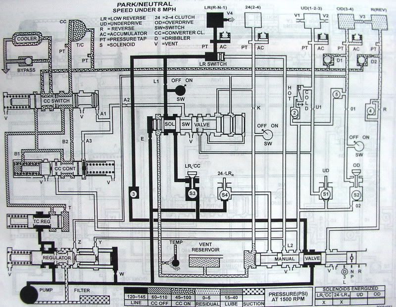
Neutral at more than 8 MPH:
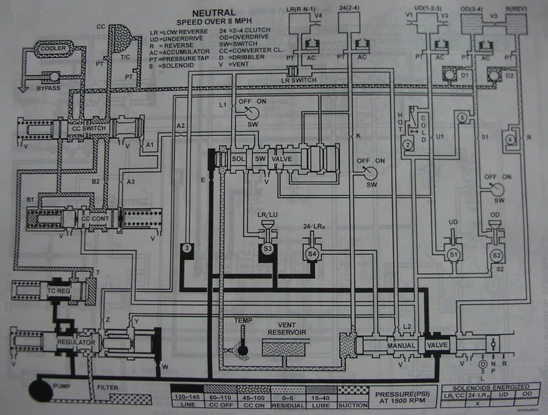
Here's Reverse Blockout at more than 8 MPH:
Also, I think it's already been handled in some of the foregoing posts, but since I'm not sure, I'll just mention that our vehicle speed is obtained from the output speed sensor.
Another probably stupid question is this: Is is possible that they solenoids should be supplied a lower voltage signal so they wouldn't be flowing so much current at 100% (grounding) duty cycle? I can't find anything in the "Wiring" FSM that shows the voltage, but I still think it might be there somewhere. I apologize in advance for my ignorance of circuits. . .
Alright, I hope these diagrams help some. Let me know if you would like anything else, or if for any reason you (Lance) don't want them shown here.
Thad
-
Bernard Fife
- Posts: 1696
- Joined: Fri Apr 04, 2008 1:28 pm
Re: Chrysler 41te Trans Control Needed By Many!
These diagrams are great, and ought to help. Thanks for posting them.
For the solenoids: since they are 1.4 Ohms DC resistance (from Steve's info), if 14 Volts is applied, since I = V/R, they will flow 14/1.4 = 10 Amps. That is a lot. So something is being done to limit the current.
They could have used resistors inline with the solenoids (in the harness perhaps) just like injector resistors (http://www.megamanual.com/v22manual/minj.htm#injresist) or they may be PWMing the outputs (http://www.megamanual.com/v22manual/minj.htm#pwm). My bet would be on PWM, since it's cheaper. And I just saw Steve posted, "55ish to 70ish, I've been told they can be pushed to 90% but I really haven't seen a reason to go past 65 or so", so PWM it is! However, we also have to figure out the PWM frequency(s) (the solenoids run best at specific frequencies, though they can be run at others). One way to do this is to google extensively and hope someone has posted the info somewhere, the other is to measure it on a factory installation using a oscilloscope.
Thanks for the info about the line pressure, Steve. Not having electronic control means we can free this high current PWM output up for other purposes.
Lance.
Re: Chrysler 41te Trans Control Needed By Many!
The range sensor switch's are just on-off switchs in the range senser plug.tjabo wrote:Steve,
This will probably turn out to be a dumb question when I look further, but are the range sensor switches JUST pressure sensor switches, or is there some set of electronic switches that sense shifter lever position, and then another set of pressure sensor switches? As usual, I'm confused!
Thad
The factory use's pressure switch's in the solenoid pack for L/R-2/4 and OD. These just feed back to
the TCM that there is or isn't pressure in the clutch packs..
I'll see what I can do on the frequencies, seems to me there's a page in the manual on it..
Re: Chrysler 41te Trans Control Needed By Many!
Awesome! ! !
Re: Chrysler 41te Trans Control Needed By Many!
A note here, I don't think PCS is useing this kind of control, just a pulse width. I'd guess
pressure would build faster with the factory logic though..
Steve
Re: Chrysler 41te Trans Control Needed By Many!
It sure looks like Lance is indicating we could do something similar to the factory-esque peak and hold style PWM with the MShift, but do you have a clue about that "inductive path opened" part of the cycle? I'm going to have to mull this over a bit and see if it makes any sense to me. . . Being the electronics dunce (at least as far as understanding circuits) that I am, I don't think there's much hope of me figuring it out!
Don't worry though, I can solder!
Thad
Re: Chrysler 41te Trans Control Needed By Many!
It seems that way, maybe that's why I need 50% or more to make it shift. It's not getting that 8ms hit to open it up...tjabo wrote:So you're saying you think the PCS software is just using a straight PWM at a consistent percentage duty cycle instead of using something like a peak and hold?
It sure looks like Lance is indicating we could do something similar to the factory-esque peak and hold style PWM with the MShift, but do you have a clue about that "inductive path opened" part of the cycle? I'm going to have to mull this over a bit and see if it makes any sense to me. . . Being the electronics dunce (at least as far as understanding circuits) that I am, I don't think there's much hope of me figuring it out!
Don't worry though, I can solder!
Thad
I'm getting ready to order electronics for the car this is going in, will the Mega shift board work as a standalone or do I need
MS2 controlling the engine to make it work?
Re: Chrysler 41te Trans Control
From our conversation, I think what you need to know is if, instead of running the engine with an MS2, you use the stock PCM (ECU for non-Chryslerites) with the AEM FIC piggyback, what inputs will need to be provided directly to the GPIO board for the MShift since it won't be able to pull data from the MS2 through the CAN bus. OR, whether it is just a lot more feasible for you to run an MS2Extra setup (which will be a lot more work for you, but will be cheaper).
Is that correct? Whether it is or is not, I have a lot of studying to do, because those seem like pretty simple questions, and I don't know the answer. . . .
Thad

