Page 1 of 1
12v+ on Shift Selector
Posted: Thu Sep 26, 2013 5:49 pm
by shaodome
So this Toyota IS300 brings 12v+ from the shift selection to the ECU/trans. I built the GPIO in accordance with the 4L60E except for the high drive circuit for the two shift solenoids. I don't believe the circuit for the 4L60E would like a 12v applied to it (unless their is some built in voltage divider/zener?).
What do I need to do to connect this shifter to the GPIO inputs?
Re: 12v+ on Shift Selector
Posted: Sat Sep 28, 2013 7:29 am
by shaodome
So I was doing some reading and it looks like all i need is a simple voltage divider to bring it from 13ish volts (engine running) down to less than 5. Attached is what I was planning on doing, except I'm going to throw a 5v Zener in there too.
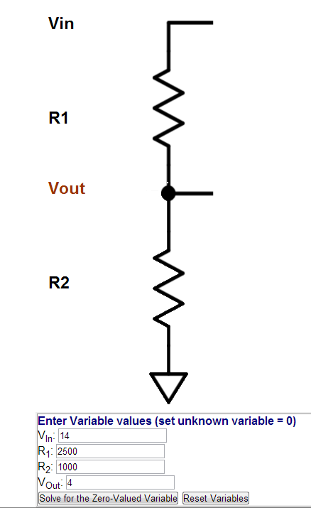
- voltage divider.PNG (20.11 KiB) Viewed 12086 times
If I'm understanding it right, this will bring the inputs for the shift selector to less than 5v. As far as Megashift is concerned the setup should be:
LEVER & SHIFT BUTTON CONFIG:
Manual Lever Mode: Digital Switches
Max Lever Position Change: 1
Digital Voltage Threshhold: 3.0 (just in case lower battery voltage it still works)
Input Patterns:
Whenever there is 12v+ supplied from the shifter on the various combonations (Park, Reverse, D, 2, L) the inputs would be HIGH for ON, correct?
Re: 12v+ on Shift Selector
Posted: Sat Sep 28, 2013 8:20 am
by Bernard Fife
shaodome,
Yes, that's the way to do it. You will need to make sure not to install any internal pull-up on the GPIO circuit (since the pull up IS the external 12V divided down).
Lance.
Re: 12v+ on Shift Selector
Posted: Sun Sep 29, 2013 3:02 pm
by shaodome
I build the circuits originally as:
Code: Select all
Install and solder a 1.0K Ohm, 1/8 Watt processor pin resistors {brown-black-red, 1.0KEBK-ND} in R27, R29, and R35.
Install and solder 330 Ohm, 1/8 Watt resistors in R21 and R25. These are the pull-up resistors for the downshift button circuit on GPI5 and the 2WD/4WD switch on GPI1.
Install and solder 5.6 Volt Zener Diodes in:
R28 - banded end goes towards Ampseal connector,
R30 - banded end goes away from Ampseal connector,
R36 - banded end goes towards Ampseal connector.
If (and only if) you are using the digital inputs for the manual gear lever determination such as with a 4L60E (as opposed to a variable voltage, Ford-style potentiometer) then you must add pull-up voltage to GPI2 (and EGT3 and EGT4 in later steps). Do this by installing a 330 Ohm resistor in R22.
Install and solder 0.1µF capacitors {399-4329-ND} in C14 and C22.
Install and solder a 0.001µF capacitor {399-4144-ND} in C16.
Since R21 and R25 are for different uses than the shift inputs I should be fine, right? I don't think the standard 4L60E has pull ups installed for the shift input circuits?
Re: 12v+ on Shift Selector
Posted: Mon Sep 30, 2013 8:46 am
by Bernard Fife
shaodome,
The 'normal' 4L60e build has the shifter on digital inputs. These are:
Input 1 (switchA) - AD0 - EGT4 (build as GPI)1 - ampseal 26
Input 2 (switchB) - AD1 - GPI2 (jumper at 25x2 header) - ampseal 6
Input 3 (switchC) - AD3 - EGT3 - ampseal 25
The 5V pull-ups for these circuits are connected by installing the following resistors:
Input 1 - EGT4 - R85
Input 2 - GPI2 - R22
Input 3 - EGT4 - R84
However, if you are using a voltage based lever, the 4L60e instructions tell you not to install R22, R84 or R85 in steps E.4 and H.5. So if you have followed those, you will be okay set up correctly for no internal pull-ups.
Lance.