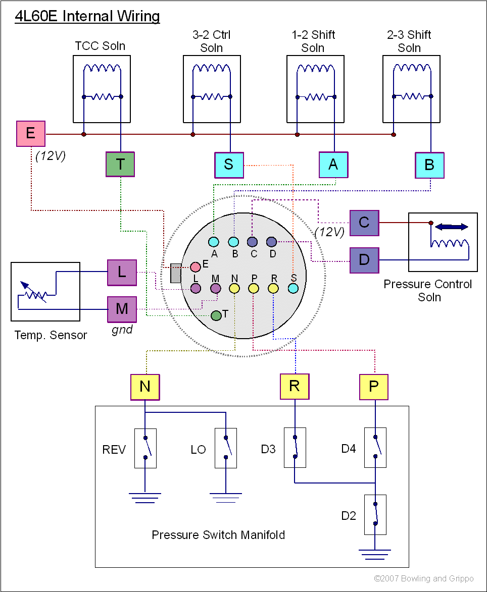
The stim duplicates the internal wiring of the 4L60E. You can see that here:

The shift and TCC solenoids are fed 12V from pin E, and each circuit is individually grounded by pins T, S, A and B. The stim replaces each of these solenoids with a LED and resistor. So you are correct, pins S and E are incorrectly swapped on the diagram.
The PC solenoid has it's own 12V supply on pin C and is grounded on pin D.
The stim doesn't need the 5.6 Volt Zener diodes or resistors, because the only load on them is the LEDs, and the inductance on these is very low.
The LED circuits ground the LEDs to light them (this was changed around after the first stim was designed). So they get either 5V or 12V, a resistor to limit current, and are grounded by GPO1, GPO2, GPO3, and GPO4 (these circuits used to supply current to the LEDs, but it was more flexible for users to have them ground instead).
<edit>I have fixed the diagrams</edit>
Lance.