Good info Lance. Looks like the ISS and slip calculation is something that may/may not be wanted. If we can do it i expect we should keep that input.
I've gone over the earlier posts and have a bit more analysis to do before making any final recommendations. Also Marty and I agreed that the speedo output should be used as a solenoid driver so if there are no objections to that it means we will have eight TO-220 size drivers powering the solenoids, including line pressure on pwm3, and all of the other 6 pwm solenoids. The TCC/reverse selector solenoid (SL) OR the trigger solenoid (SR) can be powered by the speedo output circuit using the last remaining TO-220 driver.
The remaining solenoid (SL or SR) will have to be driven using another circuit, either a repurposed input circuit or one of the four LED driver circuits. IF we use an LED circuit it would mean blanking the 3 LED display in 1st and 8th gears and we'd just take the circuit for the first LED and use it to drive the solenoid, leaving the remaining 3 to function normally. Also if this is done, the driver for the circuit used for the solenoid should be changed to a ZTX651 transistor so it will handle the higher current, should have a flyback diode added, and whatever other mods are needed for this type circuit.
I believe the alternative is to juggle the shift selector switch inputs and I will be concentrating on what configuration there looks the best as an alternative.
But Marty is caught up to where I am on the assembly and we can move forward cooperatively. I think while these last issues are being resolved we can go ahead and assemble GPI3, GPI4, VR1, and VR2.
Jim
AA80E 8-speed
-
Jim Blackwood
- Posts: 222
- Joined: Tue Dec 07, 2010 9:52 am
Re: AA80E 8-speed
Now I think I'm getting down to the gist of it. The question really is, how is it possible for us to use an input circuit such as a GPI, VR or EGT circuit as an output? Can this really be done?
If so it should make it very simple to decide on the last two drivers. But the signal conditioning circuits run the wrong way. I don't know what is inside the processor or how it's input/output lines can be configured so maybe it is possible on that side but I really need to know what modifications of the input circuits are needed to make them usable as outputs. Anybody got a link?
Jim
-
Bernard Fife
- Posts: 1696
- Joined: Fri Apr 04, 2008 1:28 pm
Re: AA80E 8-speed
Jim,how is it possible for us to use an input circuit such as a GPI, VR or EGT circuit as an output? Can this really be done?
There are two considerations:
- Can the GPIO PCB circuits be 're-purposed'? Sometimes. The input circuits were generally designed to be adaptable to be other sorts of inputs (so a VR input circuit can easily be used as a digital or analog input), but not usually to be other sorts of output circuits. However, that doesn't mean it cant be done, just that it is not as easy. For example, the VR circuits have small transistors in them that if the circuit was built appropriately could drive an external load of up to a few hundred milliamps (a relay, for example). So if you only needed an ON/OFF output, then this could work to control a solenoid through a relay. However, if I was going to do this, I would likely use the processor outputs to drive output circuits (copied from the PWM circuits) built on a small proto board (which are cheap, widely available, and easy to work with and modify). If there is enough demand, I could whip up a small dedicated PCB that would have the additional circuits on it, all of which could be PWM'd.
- Can the input pins on the processor be used as outputs? Yes, in all cases except pin PE0, the ports can be configured as either inputs or outputs (that is why they are called general purpose input/outputs, from which the GPIO board gets its name). This can be done 'on the fly' with a software setting (that changes the port's 'data direction' register) so it could be part of the MSQ for your particular application. Then within the inputs, only certain ports (a port normally, but not always, has 8 pins numbered 0 through 7) can be configured as analog-digital conversions, and only some can be timer pins (even the serial and CAN port pins can be used as outputs, though that's not very helpful for us).
I suspect you know more about this than I do, but I put it here for others that might stumble upon this thread.
Lance.
"Never wrestle with pigs. You both get dirty and the pig likes it." - George Bernard Shaw
-
Jim Blackwood
- Posts: 222
- Joined: Tue Dec 07, 2010 9:52 am
Re: AA80E 8-speed
Thanks Lance, but you give me too much credit. I just work hard at trying to understand and sometimes it pays off, sometimes it doesn't.
But to the point. That being the case it seems to be mainly a matter of selecting two ports that we can use as additional outputs which would then allow us to keep the full complement of indicator LED's and the speedo output. These two outputs can be simple on/off and would need a driver that can power an 11 ohm solenoid, so at least an amp and a half of current capacity. Of course a comfortable cushion would be a good idea, I would like to use a transistor with at least twice that capacity. Two external drivers with that size transistors shouldn't be that much of a challenge, so the issue right now is selecting the ports.
One very good possibility is the line pressure sensor circuit, EGT2 on port AD4. The line pressure sensor in this transmission does not measure line pressure, it is a switch used as a fault indicator on SL1. So it really isn't something we are likely to use. I think we should drive one of the external driver circuits with it if it will work that way.
Let me just say that I'm only beginning to grasp the significance of the pair of fixed jumpers used in the MShift applications. PEO is apparently not used. It is an input only port as I understand but GPI2 the normally associated circuit is an input also. My guess would be that it is so that AD1 can be used to process voltage based shifter position inputs? Which is something that we don't necessarily need to worry about here. If AD1 can output a signal wouldn't it make sense to use PEO as the input for GPI2 (the default) for the reverse position switch input and use AD1 to drive one of the external output circuits in this application? The AA80E uses a 4 position rotary switch with a common source (or drain, depending on how you hook it up).
The other fixed jumper PT7 to VB1 seems to be intended to switch the port PT7 from a VR input to a VB output in order to drive solenoid SL2, which is fine. But could port AD1 drive VB1 and port PT7 drive one of the off board drivers? Probably there is some other reason for it being done this way that I either haven't seen or don't remember. I only mention it because this would get us away from any fixed jumpers, and allow us to use the small block jumpers exclusively except for the two off board driver circuits which would use the removable jumper wires. I realize it would require some code modifications to make these changes so if the modifications are too much maybe we could just use one or two of the gear selector position indicator input lines instead.
Hope this makes sense, and Lance I'm relying on you to tell me if the code changes seem reasonable or not of course. As far as I'm concerned you have the final say.
Jim
-
Bernard Fife
- Posts: 1696
- Joined: Fri Apr 04, 2008 1:28 pm
Re: AA80E 8-speed
Jim,These two outputs can be simple on/off and would need a driver that can power an 11 ohm solenoid, so at least an amp and a half of current capacity.
Since these are On/Off and not PWM, one possibility is to use something like the VR input circuits as outputs to drive a standard 40 Amp relay. Typically it only take a few hundred milliamps to control the relay (the control circuit is typically around 75 Ohms, so the current won't exceed 160 milliamps or so). The relay can then switch up to 40 Amps with no issues.
Yes, though it would be any easy change to the code to have it use any other available ADC input for the voltage based gear lever sensing function.My guess would be that it is so that AD1 can be used to process voltage based shifter position inputs?
Yes, that is certainly possible.If AD1 can output a signal wouldn't it make sense to use PEO as the input for GPI2 (the default) for the reverse position switch input and use AD1 to drive one of the external output circuits in this application?
Yes, that could be done too.But could port AD1 drive VB1 and port PT7 drive one of the off board drivers?
The 4.1xx code is set up to make adding these sort of functions as straightforward as possible, so I don't anticipate any 'show stopping' problems. None of the above is hard, and the code changes aren't enormous, just a bit tedious, and like all changes they require a fair bit of testing (some of which you would have to do).
Lance.
"Never wrestle with pigs. You both get dirty and the pig likes it." - George Bernard Shaw
-
Jim Blackwood
- Posts: 222
- Joined: Tue Dec 07, 2010 9:52 am
Re: AA80E 8-speed
OK Lance, then I think that plan is feasible. I will tidy up the spreadsheet to show those changes and look for any loose ends and Marty and I can proceed with our builds based on that plan. The spreadsheet should be finished by next week and the rest of the build shouldn't take much longer, but of course we each will have to do installs and have peripheral issues so there shouldn't be much of a rush on the code changes. With both of us available for testing we can compare results.
I will proceed with the last scenario, reverting to original assignments of PEO/GPI2, AD1/VB1 with PAO and PT7 going off the board, powering SL and SR via external drivers. We may want to use a transistor driver for SR, as it will be incrementally faster than a relay and will affect shifting speed to that extent (admittedly not much but delays do add up). I will see what Marty wants to do. The relay idea is a very good one and thanks for suggesting it.
The LED drivers will remain unchanged, as will the speedo output and the shifter position switch type inputs. (All AA80E transmissions are fitted with the same shifter switch so voltage based sensing should never be needed.)
This also leaves us with AD4 as a usable input provided that we have no use of a SL1 fault sensor. So nice to have excess capacity!
Jim
-
Jim Blackwood
- Posts: 222
- Joined: Tue Dec 07, 2010 9:52 am
Re: AA80E 8-speed
OOps. PAO. Made a mistake there, that's not a free port. So it'll have to be AD4 instead. Sorry. No excess capacity I guess. Oh well.
Jim
Jim
Re: AA80E 8-speed
Hi Jim,
Hope you had a great vacation, i have been so busy with work lately that this was put on hold. Have a read over your last posts and everything seems to make sense to me. You had outlined..
http://www.msgpio.com/manuals/mshift/mode_button.gif
The Stock speed sensor will and can drive most Speedo units as there a quite a few converters on the market for toyota/lexus transmissions to drive other manufacturer/market speedos.
example
http://www.dakotadigital.com/index.cfm/ ... ct_id=126/
Marty
Hope you had a great vacation, i have been so busy with work lately that this was put on hold. Have a read over your last posts and everything seems to make sense to me. You had outlined..
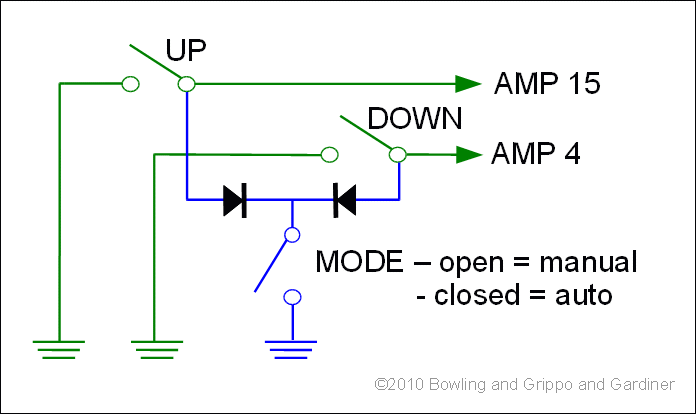
1. We are missing an Upshift input for paddle shifters as per this diagram??GPI 1-5:
GPI-4 is the brake light input, that needs to stay as is.
GPI-3 is temperature. (How badly do we need this?)
GPI-5 is downshift. I think we need this for the paddle shifters.
GPI-1 is 2/4WD, I think maybe we can use this as a solenoid output. Anyone using this transmission for 4wd applications may need to come up with something different. (You really do not need an accurate speedo in low range, is that the function of this input?)
GPI-2 is swB(Output2) Solenoid output?
http://www.msgpio.com/manuals/mshift/mode_button.gif
This may be important, as it is a safety requirement and a usefull way of diagnosis of slippage problems etc etcGPI-3 is temperature. (How badly do we need this?)
The Stock speed sensor will and can drive most Speedo units as there a quite a few converters on the market for toyota/lexus transmissions to drive other manufacturer/market speedos.
example
http://www.dakotadigital.com/index.cfm/ ... ct_id=126/
I think the function of this is to drive a 2wd/4wd solenoid switch on some 4wd transmissions?GPI-1 is 2/4WD, I think maybe we can use this as a solenoid output. Anyone using this transmission for 4wd applications may need to come up with something different. (You really do not need an accurate speedo in low range, is that the function of this input?)
Marty
-
Jim Blackwood
- Posts: 222
- Joined: Tue Dec 07, 2010 9:52 am
Re: AA80E 8-speed
Hey Guys,
I think I have a good beta of the spreadsheet for the AA80E now, at least in the MegaShift areas, subject to error checking and approval by you guys of course. I've added a section for the jumper header which I think can be helpful and color coded it green for outputs and blue for inputs. The two off board drivers can come right off the jumper header but I've not looked yet at where they will come back on the board to connect to the ampseal pins. Worst case I guess they can be wrapped and soldered.
Now I'm anything but infallable, so Lance and Marty, both of you really should take a good look at this to see if you can find any mistakes. It's a pretty large and complicated picture and about two days from now I will remember very little of it. I've given it my best shot and I hope I've got it right, but there are no guarantees so I hope you two will catch any mistakes I might have made.
Jim
- Attachments
-
- MegaShift AA80E Beta MS v3.0-MS3-MSX-IOX-GPIO .xls
- (190.5 KiB) Downloaded 1100 times
Re: AA80E 8-speed
Hi Jim,
Have just downloaded so will go over this evening and check against my wiring diagrams and other information.
Marty
Have just downloaded so will go over this evening and check against my wiring diagrams and other information.
Marty