There are 4 dedicated pulse width modulation low-side driver output circuits on the GPIO board:
Circuit | CPU Port | AMP pin number |
| PWM1 | PT4 | 31 |
| PWM2 | PT3 | 32 |
| PWM3 | PT2 | 33 |
| PWM4 | PT1 | 34 |
The pulse width modulation (PWM) circuits on the GPIO board can be used to switch ground to external devices, either ON/OFF or in varying duty cycles. While other circuits, such as the general purpose outputs, could be used for PWM control, these dedicated PWM circuits have much heavier duty transistor, and a substantial heat sink, and so are suitable for higher load devices (such as PWM idle valves, PWM transmission solenoids, etc.)
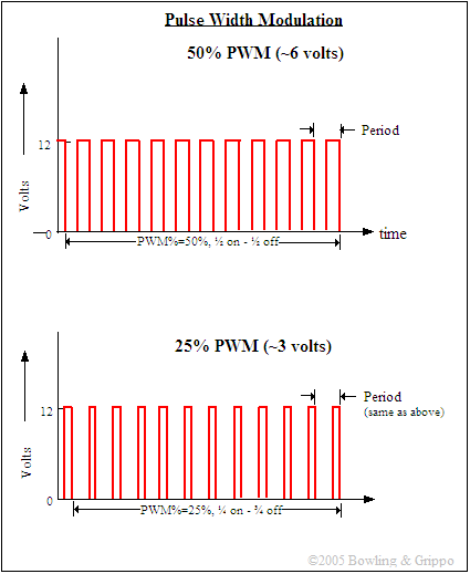
PWM works by switching the 12 volt ground to the injector on and off very rapidly (in about 0.000059 seconds!). The ratio of the "on" time to the "off" time determines the current through the injectors. However, the easiest way to think of the PWM% is as a percentage of the supply voltage, so 50% PWM on a 14 volt supply becomes effectively 7 volts on average, 28% would be 4 volts, etc.
Remember that pulse width and PWM% are two different things. Pulse width is the total duration of the signal whereas PWM% is the ratio of 'on-time' to 'off-time' within the pulse. So in the above illustration, the pulse width for both is the same, but the PWM% for the first is 50%, while for the second it is 25%.
The default transistor for the PWMx circuits is the TIP120. This is a robust NPN Darlington transistor in a TO220 package capable of flowing up to 5 Amps. The heat sink mounting allows for high current flows while keeping the transistor temperature under control.
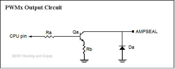
The above illustration is a general schematic. The following table gives the actual components installed in each circuit:
| Ra | Rb | Qa | Da | Ampseal | |
| PWM1 | R1 | R9 | Q1 | D7 | 31 |
| PWM2 | R2 | R10 | Q2 | D8 | 32 |
| PWM3 | R3 | R11 | Q3 | D9 | 33 |
| PWM4 | R4 | R12 | Q4 | D10 | 34 |
The 'standard' components are:
| Component | Default Values | Marking | Notes |
| Ra | 1.0 K | brown-black-red | current limit from processor |
| Rb | 1.0 | black-brown-black | for 'scoping current flow, can be jumpered |
| Qa | TIP120 (NPN) | ||
| Da | 22 Volt Zener diode | to shunt flyback spikes to ground |
To use the PWMx output circuits, you supply power (12 Volts) to the device from a switched (and fused) source, and you ground the device thorough the GPIO PWMx circuit.