Page 1 of 3
Which 'load' is used in the PC calculations?
Posted: Mon Apr 20, 2015 6:13 am
by Addicted
Lance,
As title, which 'load' variable is used in the Pressure Control table? raw MAP load from the Canbus or the load after blending TPS with MAP?
Martin
Re: Which 'load' is used in the PC calculations?
Posted: Mon Apr 20, 2015 8:14 am
by Bernard Fife
Addicted,
The instantaneous load value calculated from the MAP and adjusted TPS (based on the use selected percentage) is used to get the PC% from the table.
The adjusted TPS is adjusted by the RPM and raw TPS using the 6x6 table of course.
The PC% can also be affected by voltage and temperature corrections.
Lance.
Re: Which 'load' is used in the PC calculations?
Posted: Mon Apr 20, 2015 12:17 pm
by Addicted
hmmmm this is going to take some thought then..
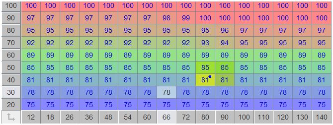
As I have lowered the TPS/load ratio down from 90% to 25% the shift has improved but slip has increased to the point of undrivability, this is because load is only in the region of 20-30 'KPA' meaning my line pressures are averaging 60% in fourth gear instead of 75-80% (see attached)
Shouldnt pressure control be based on true engine load? i.e the MAP value from canbus? its a little confusing as I clearly need to rethink my shift tables too..
Re: Which 'load' is used in the PC calculations?
Posted: Mon Apr 20, 2015 12:42 pm
by Bernard Fife
Addicted,
Couldn't you raise the PC% on the table in the lower load regions to 75-80%, something like this:
- PCpercent.JPG (61.33 KiB) Viewed 13100 times
Alternatively (
or additionally), you could use the 6x6 Load Table TPS x RPM to limit how low the TPS is allowed to go (
giving the TPS a 'MAP-like' range of values). For example, you could do this:
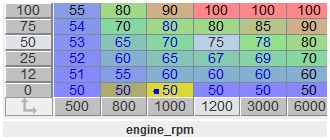
- TPS.JPG (22.74 KiB) Viewed 13100 times
This would require re-tuning the shift table, though. However getting the TPS table right in the beginning is important, it will affect many other tuning parameters. I think this is particularly difficult for you because we have made such dramatic changes from what you were initially tuning (
it might have been easier to start from scratch in some ways).
Lance.
Re: Which 'load' is used in the PC calculations?
Posted: Mon Apr 20, 2015 1:14 pm
by Addicted
The problem with modifying the table like you suggest means that the minimum pressure is 75%, which is too high for lower gears based on my datalog of the OEM installation where for instance average pressure in third is only 65%
I need to sleep on it, but I cannot help but think that PC should increase with the actual load seen by the engine/transmission and be independent of the shift conditions we've worked so hard to perfect
Re: Which 'load' is used in the PC calculations?
Posted: Mon Apr 20, 2015 1:58 pm
by Bernard Fife
Martin,
You *could* use the PC output as spare port 3. This would give you lots more options for how you want this configured, such as using raw MAP for the vertical axis (
and speed or rpm or gear, etc. for the horizontal axis).
Unfortunately the documentation isn't complete for spare port 3 usage yet, but I will work on it. There is some info here:
http://www.msgpio.com/manuals/mshift/spareport.html and here:
viewtopic.php?f=4&t=240&start=70#p3440
Lance.
Re: Which 'load' is used in the PC calculations?
Posted: Mon Apr 20, 2015 11:41 pm
by Addicted
Hi Lance,
That appears perfect actually, the functions that are lost by switching to PWM mode for SP3 are functions that I don't use anyway!
I'll start by 'copying' the existing PC table (inverted of course! 75% will become 25% etc etc) and tune from there
I'll feed back with my results.
Thanks
Martin
Re: Which 'load' is used in the PC calculations?
Posted: Tue Apr 21, 2015 10:20 am
by Addicted
Does this table look right to you Lance? its the default PC table with the values reversed i.e 92% becomes 8%
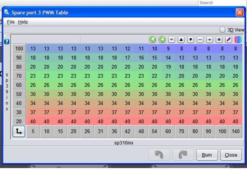
I notice the variables names arent displaying correctly, is that bug or deliberate?
Re: Which 'load' is used in the PC calculations?
Posted: Tue Apr 21, 2015 11:23 am
by Bernard Fife
Martin,
That looks about right to me.
The index variable names won't show because TS has no good way (that I know of) to show these given the options for the spare ports. It could be done with user settings (like for the *F/*C settings) but this adds addional options to an already crowded and poorly understood menu. I can look at how you can do this on an individual basis, possibly in the INI itself or a custom setup.
In the meantime, the variable should respond the changes in whatever index you have chosen, and these are also reported in a datalog (as the raw values, of course, but also specifically as sp19inx and sp39inx so you can verify the index values in use).
Lance.
Re: Which 'load' is used in the PC calculations?
Posted: Tue Apr 21, 2015 12:08 pm
by Bernard Fife
Martin,
You can display the appropriate index variable name this with a "custom.ini" file. The contents would be like the following example for changing the 9 element index (the vertical bins):
Code: Select all
[TableEditor]
   ;       table_id,    map3d_id,    "title",      page

	table = sp3table, sp3map, "Spare port 3 PWM Table - custom.INI", 2
   	  topicHelp = "http://www.msgpio.com/manuals/mshift/V5tune.html#ap"
      xBins       = sp3_16Bin, sp316inx, readonly
      yBins       = sp3_9Bin, rawMAP, readonly
      zBins       = sp3_table
      upDownLabel = "+", "-"
      gridHeight  = 0.7
      gridOrient  = 220,   0, 340
"rawMAP" is what would be displayed and used to highlight the cells, and should match the parameter you have chosen for the sp3 9 element index.
You can also change the 16 element index (to rpm, or speed, or gear, or whatever you are using for the 16 element index).
You put the custom.ini file in the Project/projectCfg folder. TS will pick up its contents next time it restarts.
The custom.ini file replaces any content in the main ini that matches. By using a custom.ini, you don't have to edit the main INI every time you update it.
I will attach the file I used above.
Lance.
