Addicted,
I am glad you are making progress.
You are correct, there is no CAN_COMMANDS option in the 2.920 settings. However, the CAN_COMMANDS must be activated using 'CAN Devices -> Configuration Settings' for any controller connected over the CANbus (MShift/GPIO in this case).
I believe that the B&G code prior to 3.8xx expects that you will always connect to the engine controller using a serial connection (directly or using a USB/serial adapter). Since it is the device connected over the CANbus that needs CAN_COMMANDS activated, it isn't used for 2.9xx B&G code. 3.830 code allows one to set CAN_COMMANDS for the engine controller (so that you could potentially connect the serial cable to either controller).
So your setup of having "Under Project Properties/Settings I have CAN_COMMANDS Deactivated(default) and have CAN_COMMANDS activated under CAN Devices, Configuration Settings" makes sense, because the engine ecu has CAN_COMMANDS deactivated (it doesn't need them as it is using serial comms to talk to TS) but the MShift controller has them activated (it definitely does need CAN_COMMANDS activated to talk to TS through the engine ECU).
I can certainly connect 2.920 to 5.094 without setting CAN_COMMANDS for the engine controller, but I do have to activate CAN_COMMANDS for MShift, of course. This configuration also works fine for grabbing the .outpc structure for MShift from the engine controller (for RPM, Load, etc.) even if the serial connection is to the GPIO board.
Lance.
VSS help please
-
Bernard Fife
- Posts: 1696
- Joined: Fri Apr 04, 2008 1:28 pm
Re: VSS help please
"Never wrestle with pigs. You both get dirty and the pig likes it." - George Bernard Shaw
Re: VSS help please
Hi Lance,
Thanks for your help with all this. Its all fixed now! engine and box running fine with 5.094 and MS2 extra!
However... 5.094 hasn't affected my original VSS issue.. comparing a 5.094 datalog with a 4.146 shows no improvement ha ha ha
Time for a cup of tea!
Thanks for your help with all this. Its all fixed now! engine and box running fine with 5.094 and MS2 extra!
However... 5.094 hasn't affected my original VSS issue.. comparing a 5.094 datalog with a 4.146 shows no improvement ha ha ha
Time for a cup of tea!
Re: VSS help please
Right then, I've started again with the part of the Audi OEM loom that deals with the VSS. Turns out that from the factory the speedo is connected directly to the reed switch speed sensor. It then processes the signal and its the speedo that then sends the signal to the transmission controller.
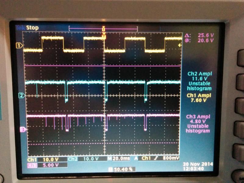
I've scoped the signals, 1 being the VSS reed switch, 2 being the output from the speedo to the GPIO and 3 being the signal at the GPIO processor after it has passed through the VR1 circuit.
The question is this, should I just the bypass the VR1 circuit entirly and 'simply' add a resistor to drop the voltage seen at the processor?
As can be seen there is noise on channel 3, this is probably what is causing my VSS/shifting issues if I assume that the code is reading those spikes whereas channel 2 is pretty clean..
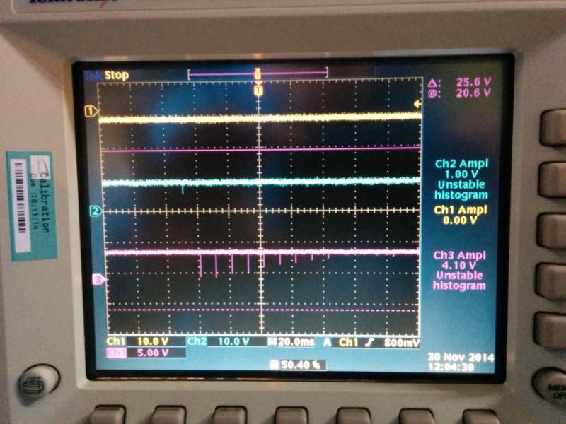
First screen is idling in 2nd, second screen is idle in Park..
I've scoped the signals, 1 being the VSS reed switch, 2 being the output from the speedo to the GPIO and 3 being the signal at the GPIO processor after it has passed through the VR1 circuit.
The question is this, should I just the bypass the VR1 circuit entirly and 'simply' add a resistor to drop the voltage seen at the processor?
As can be seen there is noise on channel 3, this is probably what is causing my VSS/shifting issues if I assume that the code is reading those spikes whereas channel 2 is pretty clean..
First screen is idling in 2nd, second screen is idle in Park..


-
Bernard Fife
- Posts: 1696
- Joined: Fri Apr 04, 2008 1:28 pm
Re: VSS help please
Addicted,
From the looks of your scope shots, I think 2 things:
- your VR circuit *may* not be built quite right or may have defective components (or it might simply be the asymmetry of the input that is causing issues), and
- the top trace certainly looks clean enough to run directly into the processor (assuming suitable voltage, etc.). You would need to built a either a voltage divider circuit (using two resistors) or use an resistor and a Zener diode clipping circuit to limit the voltage to never more than 5.0 Volts. A voltage divider gives a constant ratio of the amplitude to the source's amplitude, but may not give enough voltage to trigger the processor pin if the signal voltage drops too low (if the signal voltage is constant this isn't an issue, of course). A resistor and a Zener diode clipping circuit will give better low end response with variable amplitude signals, but it is a little trickier to design and source parts for.
Voltage Divider: http://en.wikipedia.org/wiki/Voltage_divider
Clipping circuit: http://www.electronics-tutorials.ws/diode/diode_7.html
Have you tied feeding the VSS signal into the GPIO board/VR1 (i.e. not the speedo 'processed' signal)? This is what I would try first, if this was mine.
BTW, I have code that reworks the VSS interrupts, and it seems to work well on my bench with all sorts of low amplitude and slow speed signals (but it might be a complete failure for you, only testing will tell). I'll post it here in case you want to give it a try:
Lance.
"Never wrestle with pigs. You both get dirty and the pig likes it." - George Bernard Shaw
Re: VSS help please
Thanks Lance,
I'll try feeding the channel 1 signal into the VR1 circuit first as thats pretty simple to do, although I suspect that channel 2 will be more stable at higher frequencies as the voltage appears more stable. Channel 1 voltage appears to vary, not sure why as its clearly just a pull up with reed switch grounding the line.
I've got some 4.8v zeners, was thinking of trying one with a 10k resistor on channel 2.(VR2 and VR3 are unpopulated at the moment)
I'll keep the VR1 circuit intact though as I've found that my trans actually has an ISS so I can add your slip algorythm in the future.
Martin
Re: VSS help please
In the end I fed the signal through a opto isolator (TLP621). This shows the VSS signal, the signal from the speedo as it enters the GPIO and the output from the opto..
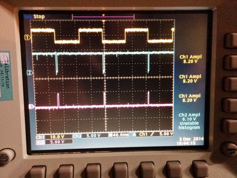
Quite suprised to find that the code isn't seeing any signal.. zero mph...

Quite suprised to find that the code isn't seeing any signal..
-
Bernard Fife
- Posts: 1696
- Joined: Fri Apr 04, 2008 1:28 pm
Re: VSS help please
Addicted,
What is the input frequency? The mph could be zero if the input frequency is too low (depending on your settings). If you post your MSQ, I will try it here with your input frequency and wave form to see if I can replicate your issue.
Lance.
What is the input frequency? The mph could be zero if the input frequency is too low (depending on your settings). If you post your MSQ, I will try it here with your input frequency and wave form to see if I can replicate your issue.
Lance.
"Never wrestle with pigs. You both get dirty and the pig likes it." - George Bernard Shaw
Re: VSS help please
Hi Lance, I see your point... however, I would point out that speedo on the dash is reading approx 20mph..
msq attached as requested
msq attached as requested
- Attachments
-
- MWB_CAN1.msq
- (45.71 KiB) Downloaded 522 times
-
Bernard Fife
- Posts: 1696
- Joined: Fri Apr 04, 2008 1:28 pm
Re: VSS help please
What input frequency did you use?
"Never wrestle with pigs. You both get dirty and the pig likes it." - George Bernard Shaw
Re: VSS help please
Sorry Lance, I don't understand, surely the whole point is that the frequency changes with speed? 