tl,
Are you testing on a bench or in a car? I have loaded your msq on my bench setup. You have 'enforce rpm checking' enabled. This is preventing shifts (on the bench at least, I am not sure how you testing). On my bench, your settings force the solenoids to be 'always on' because that what you has specified for first gear, and the trans never shifts out of first (because of the rpm checking).
When I disabled rpm checking, the code shifts appropriately with this msq, and the solenoids switch on and off as set in the 'Shift Output Patterns'. That rules out a code issue.
If you could post a datalog as well as your msq, that would be helpful (it would tell us if the code is commanding the solenoids to change, and if not, why not). I would also re-download the code from the site, and reload it onto the GPIO board in case it was corrupted anywhere in transit.
In the car, rpm checking enable is highly recommended (and is tested and works as designed), but on the bench it should be turned off because the relationship between the speed and rpm is often not appropriate for the shifts to occur. If you are testing, I would turn it off until you get this sorted.
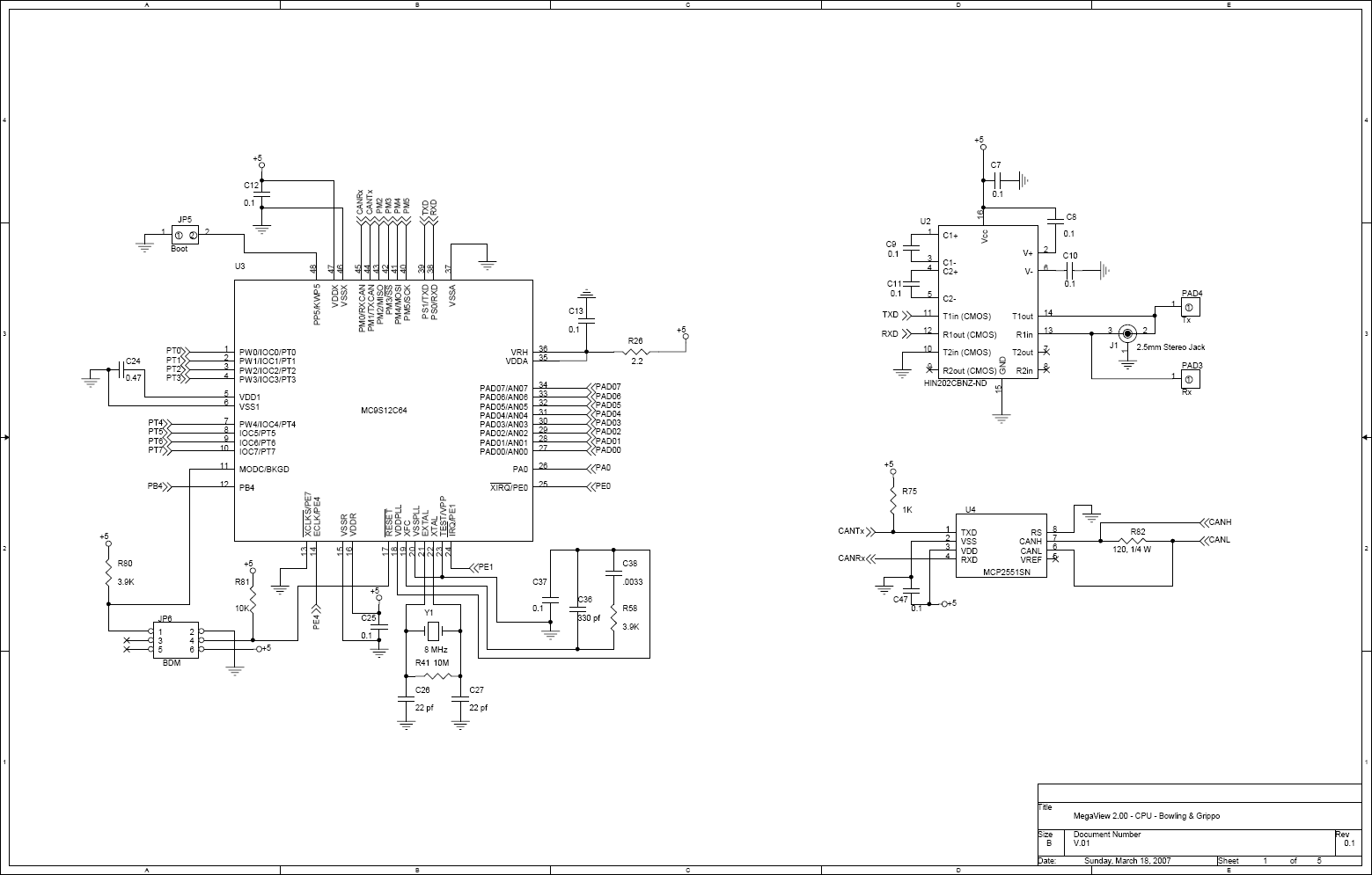
Other possible issues are a short in the PCB, or wiring. If this was mine, I would investigate this by removing the solA and solB jumpers at the 25x2 header. That should remove the 5V signal to the TIP120. If the solenoids stay on, you have a short 'downstream' of the header. The jumpers are:
- processor PE4/ circuit VB3/ Amp pin 23
- processor PM2/ circuit VB4/ Amp pin 35
I would also make sure that the solenoids are connected to the correct ampseal pins, and that the harness side of these pins are not grounded when it is not connected to the GPIO (which would indicate a wiring short).
But before doing any of that, if you have not thoroughly cleaned the PCB using 99% isopropyl alcohol (or equivalent), you should do that first.
I would also check to make sure that the processor pins for PE4 and PM2 were not shorted to adjacent pins with excess solder during manufacture. PE4 is pin #14 on the processor, PM2 is pin #43 (pin #1 is on the side of the CPU nearest the edge of the PCB, and is the one nearest the boot jumper header. The pins are numbered counterclockwise around the chip from #1).

Lance.
