Page 2 of 5
Re: 4r70w setup
Posted: Wed Jan 02, 2013 5:20 pm
by ttoptt
Sounds awesome, I'm wanting to replace my tko behind my twin turbo 351. Never thought I'd want an auto but it will be worth it with the right swap and electronics...just rather not buy that $600 Baumann! Do you foresee any major speed bumps along the way?
Re: 4r70w setup
Posted: Sun Jan 27, 2013 8:43 am
by ashford
i figured i would post this since i couldnt find it on the net. a screen shot from mitchell
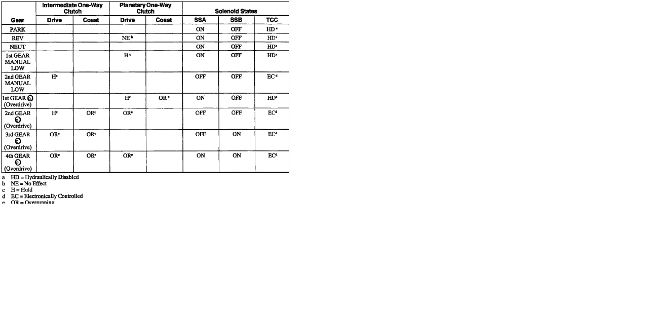
- shift pattern4r70w.png (48.12 KiB) Viewed 27347 times
Re: 4r70w setup
Posted: Sun Jan 27, 2013 10:49 am
by PSIG
ashford wrote:things i can't find on the internet
max shift pressures
transfer function for the line pressure pwm (ford measures current)
pressure sol frequency
if the shift sol's are pwmed
dithering?
tcc pwm?
also i have a 2001trans and it has a digital mlps like a gm, how will i be able to get the od switch/button to work?
Ashford -
I found your thread as I have a project coming-up ('97 4R70W with analog MLPS) that needs to be done in the next couple months, so I'm a bit anxious about finding the required info quickly. I will start looking for info as well, and I'm surprised there isn't more out there (or here). There appears to be no activity on microTCU yet, and the MSgpio sppears to be the best alternative to MS2/µSquirt. The only reference I've found in a quick search for the missing info so far is a general statement that the PWM frequency varies with line pressure. I find that very odd. I also heard at least one aftermarket controller uses ON/OFF for the TCC, even though the original control was PWM. I do not have access to a functioning OEM setup, so I'll keep searching and post any findings.
David
Re: 4r70w setup
Posted: Mon Jan 28, 2013 3:35 pm
by ashford
i have gathered some info but it is not fully complete(most from mitchel on demand) i have specs for epc and line pressure for wot and part throttle and can reverse engineer some of it. i have not found anything on frequencies yet. (said person could have mistook duty cycle with frequency).
i ditched the digital mlps since it didnt seem like it would work with a od switch on current code.
for the output shaft sensor there looks to be 2 choices a 6 hole reluctor or a 24 tooth reluctor, i have the 6 hole one. really easy to to tell what you have just pull the sensor and look.
i will get this sorted out one of these days, im doing an engine swap, turbo install building the trans all at the same time it may take me awhile.
on a side note i do have a quarterhorse on a car with a 4r70w and can get the shift and pressure data form it. the only thing i can't get is frequency, pwm=psi since ford relies on current draw instead of pwm.
Re: 4r70w setup
Posted: Fri Feb 08, 2013 10:19 pm
by PSIG
ashford wrote:the only thing i can't get is frequency, pwm=psi since ford relies on current draw instead of pwm.
Not sure I follow "current draw"? If (it seems) EPC and TCC are PWM controlled, why can't we get PWM frequencies and duty cycles under various conditions?
David
Re: 4r70w setup
Posted: Sun Feb 17, 2013 1:40 pm
by ashford
psig all gm transmissions that i have hooked a scantool or tuner to their "force" solenoid has a resistor on it and the ecu measures voltage across this resistor. the tuning software uses amps (voltage across resistor?) as determining factor for pressure. they have a scale where X amps = X pressure then the tuning parameters are in psi. ford is similar but uses ADC counts instead of amps on their scale.
i tested my 97 f150 today i don't like what i see. i had to double check with a scope. i had a voltmeter hooked up that measures dc and frequency. at idle duty cycle is about 55% at a frequency 6.5khz. no joke i had the same results with the scope. duty cycle decreases with load and frequency increases as dc goes down. i saw 10khz in gear 1/2 throttle and dc around 25%. a quick drive and i saw upto 20khz at full load. to be doubly sure i didn't hook up to a tach feed i drove at 3krpm in first and the frequency was 7khz.
granted this is a newer trans than the origional design they say you can always put a newer trans on an older ecu but not vice versa. as far as i know there are 3 different pc sol's the origional @1.3 ohms after 95 @3.5 ohms and the 99+ that is 10 ohms.
Re: 4r70w setup
Posted: Tue Feb 19, 2013 10:13 am
by ashford
looking at the code docs it seems frequency i limited to just under 2khz. if the higher frequencies are needed by the pc sol would a product like jeans pwm multiplier work?
http://www.msgpio.com/pwm_converter/index.html
Re: 4r70w setup
Posted: Mon Apr 22, 2013 5:53 am
by ashford
a little update. i got the engine running ran into lots of problems getting things to work correctly as i have a brand new motor i didn't want a bunch of run time without load on it so i was just trying to get the pc sol working and manual shift. ended up with a ampseal terminal not in all the way and had to turn off rpm checking. during the test i tried 1.416, there is something completetly wrong with it. current gear is flickering between 0 and 1 and pwm(pc) fluctuating between 100 and 60. i reverted back to 1.404 an things seem to work as intended. hope to get it on the wheels and driven sometime this week
Re: 4r70w setup
Posted: Mon Apr 22, 2013 6:42 am
by Bernard Fife
i tried 1.416 (sic), there is something completetly wrong with it. current gear is flickering between 0 and 1 and pwm(pc) fluctuating between 100 and 60
ashford,
I will have a look.
However, you may need to adjust your voltages (assuming you are using the Ford style shift lever). The calculations were corrected a while ago (around 4.112, see:
viewtopic.php?f=4&t=240&start=60#p3184).
If you had set up the shift lever voltages with previous code, they might not be right with the newer codes. However, the newer codes are correct (the older ones definitely had issues), and your settings won't have to change again for future codes.
Lance.c
Re: 4r70w setup
Posted: Mon Apr 22, 2013 6:55 am
by ashford
yep i had to change the input voltages they did not import from my old msq(difference report in ts). another thing i noticed is that input 1 moved very slowly and if i went to drive from neutral vs 2nd it settled on a slightly different voltage about .1 v difference.
my take on the pwm flickering is it is intermitently detecting the engine running, that may or may not of affected the current gear setting.
i had a second question though, i have pin 17 going to the serial db9 and pin 18 for "signal return" 19 and 20 to ground source. after reading the vss page i noticed that 17 is for signal only. is pin 17 on a different ground plane in the board?