Page 1 of 1
GPI4 Brake sense circuit - voltage or ground?
Posted: Sat Oct 18, 2014 1:00 pm
by mcneil
My electrical skill level isn't the greatest, but just wondering if I'm missing something with the 4L60e instructions and the trans stim.
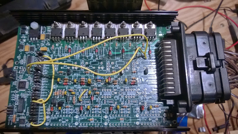
Everything is assembled per the build guide. The board looks like this (disregard jumpers, I've been testing out circuits):
With everything connected on the bench, the brake switch on the trans stim grounds Ampseal pin 3. But the brake status on tunerstudio doesn't respond.
If GPI4 is a voltage divider circuit, how does it sense the brake switch being grounded?
For reference, this is in a
Jeep TJ, brake switch has 3 poles, two for the ECU and one for stop lights. My plan was to use one of the ECU poles which connect to ground as the brake sense input for the MegaShift.
Re: GPI4 Brake sense circuit - voltage or ground?
Posted: Sat Oct 18, 2014 1:28 pm
by Bernard Fife
mcneil,
The circuit looks right to me. You might check for cold solder joints in the circuit and at the ampseal connector; and 25x2 header as well.
I would also check there there is a signal at the GPI4/AD7 jumper on the 25x2 header. Make sure you have a grounded voltage of less than 1.75 Volts, and an active signal of at least 3.25 Volts on the jumper pin on the GPI4 side.
If GPI4 is a voltage divider circuit, how does it sense the brake switch being grounded?
The circuit should be attached to a switch that provides either 12V or ground (or floating). But it cannot be floating and ground, that won't work in the standard build as it has no pull-up voltage source attached. Instead the brake electrical system voltage is used as the pull-up. The circuit divides the 12V down to 5V, and this is used as 'Brake ON' for the controller, and removing the 12V allows the circuit to drop to 0V and this is recognized as Brake OFF'. (
The polarity can optionally be reversed in the user settings, of course).
If the problem with the brake indicator isn't in the soldering or voltage levels, it could be with the stim, the circuit, the code, or the INI. If you post your MSQ and a datalog I could look more closely.
Lance.
Re: GPI4 Brake sense circuit - voltage or ground?
Posted: Sat Oct 18, 2014 3:20 pm
by mcneil
Thanks Lance, while I did find one bad joint, fixing it didn't seem to change anything. I confirmed that Ampseal 3 and GPI4 are just floating or grounded.
Black is the existing circuit, I'm going to add the part in red as a pull-up. Does that look right to you?
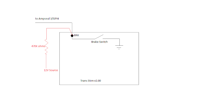
Edit: Can I do this by using something in R24?
Re: GPI4 Brake sense circuit - voltage or ground?
Posted: Sat Oct 18, 2014 4:41 pm
by mcneil
One more question - why is the brake switch on the trans stim a 2-pole? One pole grounds the brake signal, what does the other do?
Re: GPI4 Brake sense circuit - voltage or ground?
Posted: Mon Oct 20, 2014 2:13 am
by Addicted
The brake circuit expects to see 12v when brakes applied, thats why its a voltage divider circuit to drop ~12v to a safe <5v..
Simplest thing would be to rebuild the circuit like, for instance, the table switching circuit..
Re: GPI4 Brake sense circuit - voltage or ground?
Posted: Mon Oct 20, 2014 6:22 pm
by mcneil
Addicted, that's the line I was thinking, but was wondering why the 4L60e build guide would say build it as 12V sense when the Trans Stim was setup like that.