Bench testing GPIO for 4l60e

A forum for discussing applications and implementations of the MegaShift transmission controller code for the GPIO from B&G. This can control up to 8-speeds and 6 shift solenoids (plus a 16x9 table for controlling a PWM line pressure valve). It has manual and fully automatic modes (16x9 load x speed table), with under and over rev-limit protection, and full data logging of all inputs and outputs (among many other abilities). A TransStim to test your completed board is also available.
Bernard Fife
Posts: 1696
Joined: Fri Apr 04, 2008 1:28 pm

Re: Bench testing GPIO for 4l60e

Post by Bernard Fife »

John,

The stim duplicates the internal wiring of the 4L60E. You can see that here:

Image

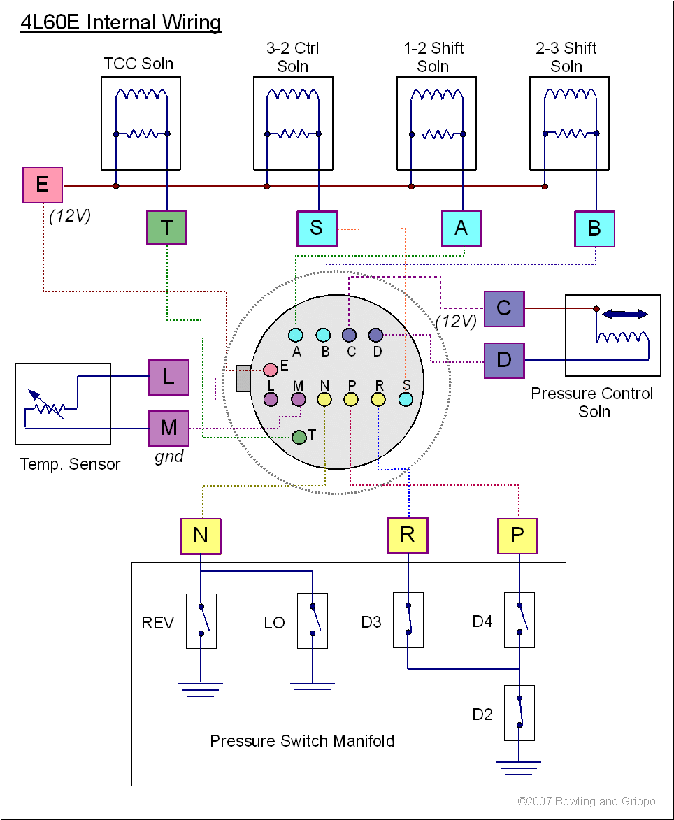
The shift and TCC solenoids are fed 12V from pin E, and each circuit is individually grounded by pins T, S, A and B. The stim replaces each of these solenoids with a LED and resistor. So you are correct, pins S and E are incorrectly swapped on the diagram.

The PC solenoid has it's own 12V supply on pin C and is grounded on pin D.

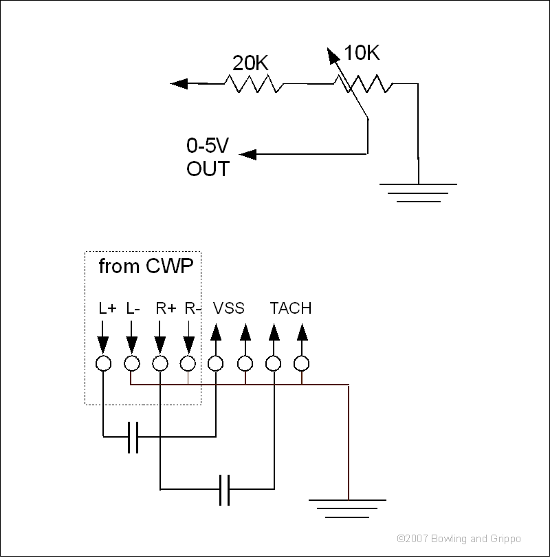
The stim doesn't need the 5.6 Volt Zener diodes or resistors, because the only load on them is the LEDs, and the inductance on these is very low.

The LED circuits ground the LEDs to light them (this was changed around after the first stim was designed). So they get either 5V or 12V, a resistor to limit current, and are grounded by GPO1, GPO2, GPO3, and GPO4 (these circuits used to supply current to the LEDs, but it was more flexible for users to have them ground instead).

<edit>I have fixed the diagrams</edit>

Lance.
"Never wrestle with pigs. You both get dirty and the pig likes it." - George Bernard Shaw
jdrapersys
Posts: 12
Joined: Wed Mar 16, 2011 10:20 am

Re: Bench testing GPIO for 4l60e

Post by jdrapersys »

Lance,

Thanks again. That clears up almost everything. I'm still unclear on the purpose of the circuit with the pot and the 20K resistor in
http://www.msgpio.com/manuals/mshift/4L60E_stim3.gif . It looks like the left side of the 20K resistor should be supplied with +5V , but what connects to 00-5V out.

Again many thanks for all you patience and help.
John
Bernard Fife
Posts: 1696
Joined: Fri Apr 04, 2008 1:28 pm

Re: Bench testing GPIO for 4l60e

Post by Bernard Fife »

John,

That circuit is there for people who want to simulate a 0-5V 'non-CAN' load signal, or who want to datalog a 0-5V input signal on one of the unused inputs.

Lance.
"Never wrestle with pigs. You both get dirty and the pig likes it." - George Bernard Shaw
jdrapersys
Posts: 12
Joined: Wed Mar 16, 2011 10:20 am

Re: Bench testing GPIO for 4l60e

Post by jdrapersys »

Lance,

Thanks again. I've almost finished testing and am about to start shopping for a used 4l60e transmission. The transmission will go in my 1967 Camaro. I am unsure of exactly what I should try to find. I think the LU feel is not something one would want in a sporty car. I don't think I will mind feeling when the gears change. I know I must have a transmission with a TCC, but I don't know what options there are for PWM. If you could buy any 4l60e you wanted, what years and vehicles would you choose?

I know I will need to get a console gear selector from a newish Camaro and a crossmember from someone like http://www.transmissioncenter.org/Class ... on_Kit.htm as well as speedometer parts. Are there other things I should look for at the wrecking yard?

Very best regards,
John
Bernard Fife
Posts: 1696
Joined: Fri Apr 04, 2008 1:28 pm

Re: Bench testing GPIO for 4l60e

Post by Bernard Fife »

John,

There are certainly people who know a lot more about these transmissions than I do, so hopefully they will share their opinions.

In general, GM tends to develop all their parts over the production lifecycle, so for example a late 4L60E is propbably a better, stronger trans then an early one, and a 4L65E is better still.

The 4L60E I used was from an Astro Van (from 93, I believe). These (and the identical S10 units) seem cheap and common as dirt. I completely rebuilt mine, and used upgrade parts everywhere. I did all the things recommended here: http://www.msgpio.com/manuals/mshift/mods.html

On mine I had to swap the tailshaft housing and shorten the output shaft by 1 inch, but that's only because it was going into a C4 Corvette. You shouldn't have to do that.

For the PWM, it doesn't really matter. The defaults are for the early trans, but are easily changed.

Lance.
"Never wrestle with pigs. You both get dirty and the pig likes it." - George Bernard Shaw
jdrapersys
Posts: 12
Joined: Wed Mar 16, 2011 10:20 am

Re: Bench testing GPIO for 4l60e

Post by jdrapersys »

Thanks again Lance,

Has anyone written about shrink wrapping the various sets of wires that come out of the AMPseal? If I'm correct there will be 7 or 8 bundles. The big 12 or 13 wire bundle to the transmission, a 3 wire bundle to the manual shifting switches, the 4 wire bundle to the external LEDs, a 3 wire bundle for the serial connection, a 2 wire bundle for a CAN connection, a 2 wire bundle for the VSS, and a 3 wire bundle to the line pressure sensor. And then perhaps a 3 wire bundle to chassis ground.

I am wondering if others have shrunk wrapped the bundles separately and what their wire harnesses have looked like. To start I found a set of numbered tape strips to label the ends of the wires with the AMPseal location they came from, but that's as far as I've gone so far.

Best regards,
John
Post Reply